EE-SPZ401-A Omron, EE-SPZ401-A Datasheet - Page 3
EE-SPZ401-A
Manufacturer Part Number
EE-SPZ401-A
Description
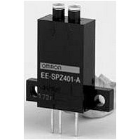
Optical Sensor (Switch) Reflective
Manufacturer
Omron
Series
-r
Datasheet
1.EE-SPZ301-A.pdf
(5 pages)
Specifications of EE-SPZ401-A
Output Current
80mA
Sensor Output
TTL LO
Supply Voltage Range Dc
5V To 24V
Sensor Housing
Rectangular
Sensor Input
Optical
Output Type
Transistor
Supply Voltage Max
24VDC
Switch Terminals
Connector
Supply Voltage Min
5VDC
Rohs Compliant
Yes
Sensing Distance
7.874" (200mm)
Sensing Method
Retroreflective
Sensing Object
Mirror
Output Configuration
NPN - Open Collector/Light-ON
Sensing Light
Infrared
Mounting Type
Through Hole
Current - Supply
15mA
Voltage - Supply
5 V ~ 24 V
Package / Case
PCB Mount
Features
Supports Connection With PLCs
Sensing Range Max
200mm
Lead Free Status / RoHS Status
Lead free / RoHS Compliant
Available stocks
Company
Part Number
Manufacturer
Quantity
Price
Company:

Part Number:
EE-SPZ401-A
Manufacturer:
OMRON
Quantity:
1 000


I/O Circuits
NPN Output
Safety Precautions
Refer to Warranty and Limitations of Liability.
This product is not designed or rated for ensuring
safety of persons either directly or indirectly.
Do not use it for such purposes.
Make sure that this product is used within the rated ambient
environment conditions.
● Wiring
• Connection is made using a connector. Do not solder to the pins
• When extending the cable, use an extension cable with conductors
• To use a cable length longer than 2 m, attach a capacitor with a
• Make sure the total length of the power cable connected to the
(leads).
having a total cross-section area of 0.3 mm
must be 2 m maximum.
capacitance of approximately 10 µF to the wires as shown below.
The distance between the terminal and the capacitor must be within
2 m. (Use a capacitor with a dielectric strength that is at least twice
the Sensor's power supply voltage.)
product is less than 10 m even if a capacitor is inserted.
EE-SPZ401-A
EE-SPZ301-A
Model
Precautions for Correct Use
OUT
Output configuration
2 m max.
Light-ON
A capacitor of
10 µF min.
Dark-ON
WARNING
5 to 24 VDC
0 V
+
−
2
. The total cable length
Extension cable
Light indicator
(red)
Output
transistor
Load 1
(relay)
Load 2
Light indicator
(red)
Output
transistor
Load 1
(relay)
Load 2
Timing charts
Interrupted
Interrupted
Releases
Operates
Operates
Releases
Incident
Incident
OFF
OFF
OFF
OFF
ON
ON
ON
ON
H
L
H
L
∗ Voltage output (when the sensor is connected to a transistor circuit)
Light indicator
(red)
Main
circuit
1.5 to 3 mA
Output circuit
OUT
Ic
Load 2
Load 1
EE-SPZ-A
∗
5 to 24 VDC
3
Related parts for EE-SPZ401-A
Image
Part Number
Description
Manufacturer
Datasheet
Request
R

Part Number:
Description:
OPTO SENSOR SLOT TYPE 5MM
Manufacturer:
Omron
Datasheet:

Part Number:
Description:
Optical Sensor (Switch) Transmissive / Slotted Interrupter
Manufacturer:
Omron
Datasheet:

Part Number:
Description:
PHOTOMICROSENSOR, TRANSISTOR
Manufacturer:
Omron
Datasheet:

Part Number:
Description:
SENSR OPTO SLOT 3.4MM TRANS THRU
Manufacturer:
Omron
Datasheet:

Part Number:
Description:
OPTO SENSOR SLOT TYPE 3MM
Manufacturer:
Omron
Datasheet:

Part Number:
Description:
SENSOR OPTO TRANS 4.4MM REFL PCB
Manufacturer:
Omron
Datasheet:

Part Number:
Description:
OPTO SENSOR REFLECT TYPE 4MM
Manufacturer:
Omron
Datasheet:

Part Number:
Description:
PHOTO MICROSENSOR :
Manufacturer:
Omron
Datasheet:

Part Number:
Description:
SENSOR OPTO TRANS 3.5MM REFL PCB
Manufacturer:
Omron
Datasheet:

Part Number:
Description:
PHOTO MICROSENSOR
Manufacturer:
Omron
Datasheet:


Part Number:
Description:
PHOTO MICROSENSOR
Manufacturer:
Omron
Datasheet:
Part Number:
Description:
PHOTO MICROSENSOR :
Manufacturer:
Omron
Datasheet:

Part Number:
Description:
PHOTO MICROSENSOR
Manufacturer:
Omron
Datasheet:

Part Number:
Description:
PHOTO MICROSENSOR
Manufacturer:
Omron
Datasheet: