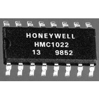
HMC1022 Honeywell Microelectronics & Precision Sensors, HMC1022 Datasheet - Page 9

HMC1022
Manufacturer Part Number
HMC1022
Description
Magnetic Sensor
Manufacturer
Honeywell Microelectronics & Precision Sensors
Datasheets
1.HMC1021.pdf
(15 pages)
2.HMC1022.pdf
(15 pages)
3.HMC1022.pdf
(15 pages)
4.HMC1022.pdf
(15 pages)
Specifications of HMC1022
Sensitivity Range
1mV/V/G
Sensor Output
Voltage
Terminal Type
PCB Thru Hole
Output Type
Differential
Sensor Terminals
SMD Gull Wing
Leaded Process Compatible
No
Magnetic Field Max
6G
Axis Configuration
Two
Lead Free Status / RoHS Status
Lead free / RoHS Compliant
Available stocks
Company
Part Number
Manufacturer
Quantity
Price
Company:
Part Number:
HMC1022
Manufacturer:
honeywell
Quantity:
12 800
Part Number:
HMC1022
Manufacturer:
HONEYWE
Quantity:
20 000
Part Number:
HMC1022-TR
Manufacturer:
HITTITE
Quantity:
20 000
Single Clock Circuitry— Some form of clock is needed to
trigger the set and reset pulses (Figure 6) to create the
switching signal. The circuit shown in Figure 8 can be used
to create a strong (>4Amp) pulse. The diodes, resistors,
capacitors and inverters basically create the TRS and the
TSR delays. Now a single signal (Clock) can trigger a set or
reset pulse. The minimum timing between the rising and
falling edges of Clock are determined by the 25KΩ and 1nF
time constant. That is, the minimum high and low time for
Clock is ≈25 µs.
Micro Processor— The circuit in Figure 9 generates a strong
set/reset pulse (>4 Amp) under microprocessor control. The
Figure 6—Single Clock Set/Reset Timing
RESET
SET
Clock
S/R
Clock
S/R
5V
T
T
T
T
PW ≈ 2 µsec
RS ≥ 5 µsec
SR ≥ 5 µsec
RS
9
5V
16V
14
16V
7
5V
Figure 9—Set/Reset Circuit With Microprocessor Control (1001/1002)
Figure 8—Single Clock Set/Reset Pulse Circuit (1001/1002)
8
•HMC2003 contains one HMC1001 and one HMC1002; together they make the 3-axis sensor.
Three S/R straps are in serial, the total resistance is ~4.5Ω.
set
set
-16V
1N4001
-16V
T
PW ≈ 2 µsec
25K
reset
reset
3
74HC04
1nF
T
25K
T
SR
PW
4
1
5
1nF
RESET
SET
2
6
LINEAR MAGNETIC FIELD SENSORS
10K
2N3904
9
25K
SET and RESET signals are generated from a
microprocessor and control the P and N channel HEXFET
drivers (IRF7105). The purpose of creating the TRS and the
TSR delays are to make sure that one HEXFET is off before
the other one turns on. Basically, a break-before-make
switching pattern. The current pulse is drawn from the 4.7
µF capacitor. If the 5V to 20V converter is used as shown in
Figure 7, then the resultant noise and droop on the 16-20V
supply is not an issue. But if the 16-20V supply is used
elsewhere in the system, then a series dropping resistor
(≈500Ω) should be placed between the 4.7µF capacitor and
the supply.
10K
2N3904
0.1µF
25K
25K
+16 to 20V
4
2
0.1µF
25K
+16 to 20V
0.22µF*
5V
* Use tantalum capacitors
3
1
5,6
7,8
4
2
Figure 7—5V to 20V Converter
2µF
4.7µF (3)
2
1
8
7
5
3
1
0.22µF (2)
(1) HEXFETs with ≈0.2Ω Ron
(2) 0.22µF Tantalum or a
(3) Tantalum, low R
C1+
C1-
SHDN
GND
Vcc
5,6
7,8
MAX662A
0.68 µF Ceramic CK06
4.7µF (1)
S/R
(1) Tantalum, low R
(2) HEXFETs with ≈0.2Ω Ron
0.22µF
S/R strap @ 4.5Ω typ.
Vout
C2+
C2-
17
3A peak (min.)
1µF
HMC2003
S/R
3
4
6
S/R strap @ 4.5Ω typ.
1
17
3A peak (min.)
1N5818
0.22µF*
HMC2003
*
1µF
12V
1
*
20V
1µF


