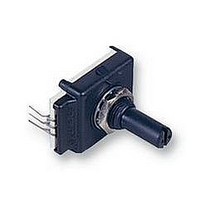
ECW0J-B24-AC0006 Bourns Inc., ECW0J-B24-AC0006 Datasheet - Page 2

ECW0J-B24-AC0006
Manufacturer Part Number
ECW0J-B24-AC0006
Description
ENCODER, 6CYCLES
Manufacturer
Bourns Inc.
Specifications of ECW0J-B24-AC0006
Svhc
No SVHC (15-Dec-2010)
Encoder Resolution
24
Operating Temperature Range
+1°C To +125°C
Rotational Speed
120rpm
Shaft Length - Metric
19mm
Contact Current Rating
10mA
Contact Current Rating @10v
10mA
Pulses Per Revolution
6 PPR
Number Of Detents
24
Termination Style
Solder Pin
Output
2 bit Gray Code
Shaft Type
1/4 in Diameter Plain with Inserted Slot
With Switch
Without
Contact Voltage Dc Max
350V
Dielectric Strength Vac
1000V
External Depth
27.6mm
Rohs Compliant
Yes
Lead Free Status / RoHS Status
Lead free / RoHS Compliant
PANEL HOLE DIMENSIONS
Bushing Mounted
DIGITAL CONTACTING
The Digital Contacting Encoder is commonly referred to by such
names as Digital Panel Control, Bit Switch, Gray Switch and Digital
Switch. All such names are synonymous with a device whose output
is a digital gray code signal, rather than a conventional potentiometric
voltage ratio output.
The advantage of the Digital Contacting Encoder is that it permits the
direct entry of digitized analog data into a digital circuit without A/D
BUSHING MOUNTED - HOUSING A
W style bushing shown.
Shaft lengths "L" for B, C, R and Y styles
24 = .750" (19mm)
36 = 1.125" (28.5mm)
PCB BRACKET MOUNTED - HOUSING B
Dimensions not given are the same as Bushing Mounted.
SNAP-IN MOUNT - Housing G
(.285 .010)
7.23 0.25
(.226 .010)
5.74 0.25
Shaft Style B
4 PLCS.
(.030)
(.125)
(.063)
(.249 + .001/– .003)
3.17
.76
6.32 + 0.03/– 0.07
ECW - Digital Contacting Encoder
1.6
13.08
(.515)
DIA.
(.375)
9.5
DIA.
(.335)
8.51
(.047)
(.355)
1.19
9.02
(.060)
(.250)
1.52
"L"
6.35
(.360)
(.354)
8.99
9.1
"D" DIMENSION EXTENDS FROM SHAFT END TO BUSHING FACE
"D" = (SHAFT LENGTH, FMS) – (BUSHING LENGTH)
DIA.
DIA.
Shaft Style C
(.218 .003)
5.54 .076
(.874 .010)
22.2 0.25
"D"
(.250 .010)
6.35 0.25
(.249 + .001/– .003)
PCB MOUNTING DIMENSIONS
(Housing Styles B and E)
6.32 + 0.03/– 0.07
23.37
A C B
(.92)
(.335)
8.51
(.930)
23.6
(.375)
(.600)
9.53
15.2
(.155 + .002/ – .001)
(.437)
DIA.
3.94 + .051/ – .025
11.1
(.060)
1.52
(.672)
(1.122 .010)
Shaft Style J
17.07
(.578 .020)
28.5 0.25
"L"
(.250)
14.7 0.5
C L
6.35
(.354)
"D"
M9 X 0.75-6g SPL
(1.149 .010)
9.0
(.047)
29.18 0.25
1.2
DIA.
(.100)
DIA. 7 PLCS.
DIA.
(.450)
2.54
11.4
"L" Dim. = 1.125 or .750
SOLDER HOLES - HOUSING C
Dimensions not given are the same as Bushing Mounted.
TYP.
conversion. The two (2) channel gray coded signal of this incremental
encoder allows the user’s decoder circuit to sense analog direction of
rotation, as well as up-down counter capabilities . . . all without the
time and cost required for A/D conversion. This approach can reduce
memory overhead, wiring and wiring interconnects, and can provide
greater MPU program speed.
(.187 .003)
4.75 .076
3PLCS.
(.025)
.635
DIA.
(.058)
1.47
DIA.
Shaft Style R
(.578 .020)
14.7 0.5
(.063)
1.6
CHANNEL A
(.874 .010)
(.200)
5.08
22.2 0.25
DIA.
(.100)
(.320)
2.54
8.1
COMMON
A C B
8 X
PCB MOUNTING DIMENSIONS
CHANNEL B
(.038)
(.047)
.97
1.19
2 X
A C B
Specifications are subject to change without notice.
(.236)
6.00
DIA.
3 PLCS.
R
(.100)
.036
2.54
(.446)
11.33
SLOT DEPTH ("Y" SHAFT)
DIA.
3 X
1" LENGTH
FOR TOLERANCES NOT SHOWN
.XX = .010
.XXX = .005
SHAFT DIMENSIONS 1/32"
DIMENSIONS ARE:
(0.042)
(.893)
(.437)
22.68
1.07
11.1
Shaft Style Y
(1.090 .01)
27.69 0.25
A
C
(.429)
10.90
(.062)
(5.20)
1.57
14.7
B
(.100)
(1.122 .010)
2.54
28.5 0.25
FOR SHAFTS 1" LENGTH
(.482)
12.24
(3.80)
9.65
(0.630)
(.200)
5.08
(INCHES)
16.0
METRIC
21.11
(.831)
FOR SHAFTS
(.778)
19.76
(.185)
4.7
DIA.


