HY 20-P LEM, HY 20-P Datasheet - Page 2
HY 20-P
Manufacturer Part Number
HY 20-P
Description
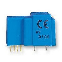
CURRENT TRANSDUCER, 20A
Manufacturer
LEM
Datasheet
1.HY_10-P.pdf
(2 pages)
Specifications of HY 20-P
Current Measuring Range Ac
DC, AC, Pulsed, Mixed
Current Measuring Range Dc
DC, AC, Pulsed, Mixed
Operating Frequency Range
DC To 50kHz
Supply Voltage Range Dc
12V To 15V
Sensor Output
Voltage
Accuracy
1%
Response Time
3µs
Svhc
No SVHC (15-Dec-2010)
Accuracy %
1%
Current Consumption
10mA
Rohs Compliant
Yes
Lead Free Status / RoHS Status
Lead free / RoHS Compliant


061027/8
Dimensions HY 5..25-P
LEM reserves the right to carry out modifications on its transducers, in order to improve them, without prior notice.
PCB MOUNTING DIMENSIONS
HY 5 to15-P
HY 20 to 25-P
HY 20 to 25-P
(in mm. 1 mm = 0.0394 inch)
3 x 2.54
3 x 2.54
3 x 2.54
3±0.5
3 x 2.54
(0.5)
1 2 3 4
4 holes dia 1
12.0
JA PAN
18.0
32.0 Max.
36.0 Max.
10±0.3
10±0.3
10
10
(in mm ±0.1, hole -0, +0.2)
(g)
HY 20 - P
HY 10 - P
2 holes dia. (e)
5
holes dia (e)
HY 5-P
8.5±0.3
8.5±0.3
( d)
45059
8.5
9639
9639
(
8.5
d
JP2
x2)
6
(g)
Safety
This transducer must be used in electric/electronic equipment
with respect to applicable standards and safety requirements
in accordance with the following manufacturer's operating
instructions.
Caution, risk of electrical shock
When operating the transducer, certain parts of the module can
carry hazardous voltage (eg. primary busbar, power supply).
Ignoring this warning can lead to injury and/or cause serious
damage.
This transducer is a built-in device, whose conducting parts
must be inaccessible after installation.
A protective housing or additional shield could be used.
Main supply must be able to be disconnected.
PIN ARRANGEMENT
HY 5 to 15-P
Type
HY 05-P
HY 10-P
HY 12-P
HY 15-P
HY 20-P
HY 25-P
2 --15V
3 OUTPUT
4 0V
5 PRIMARY IN
6 PRIMARY OUT
1 +15V
(a)±0.3
3.9±0.3
mm mm mm mm
1.1
1.4
1.5
1.5
1.4
1.5
a
(0.3)
12 Max.
0.7 1.2
d
1.1 1.6
1.4 2.0
1.4 2.0
1.2 1.8 1.4
1.4 2.0 1.6
e
g
--
--
--
--
www.lem.com
Page 2/2
Related parts for HY 20-P
Image
Part Number
Description
Manufacturer
Datasheet
Request
R

Part Number:
Description:
SENSOR CURRENT 10A -+15V 6PIN
Manufacturer:
LEM USA Inc
Datasheet:
Part Number:
Description:
SENSOR CURRENT 25A -+15V 6PIN
Manufacturer:
LEM USA Inc
Datasheet:
Part Number:
Description:
SENSOR CURRENT 5A -+15V 6PIN
Manufacturer:
LEM USA Inc
Datasheet:
Part Number:
Description:
SENSOR CURRENT 15A -+15V 6PIN
Manufacturer:
LEM USA Inc
Datasheet:
Part Number:
Description:
SENSOR CURRENT 50A -+15V 6PIN
Manufacturer:
LEM USA Inc
Datasheet:

Part Number:
Description:
DEVELOPMENT KIT, LTS25NP SERIES
Manufacturer:
LEM
Datasheet:

Part Number:
Description:
SENSOR CURRENT 200A TH
Manufacturer:
LEM USA Inc
Datasheet:
Part Number:
Description:
Current Transducer
Manufacturer:
LEM
Datasheet:
Part Number:
Description:
Current Transducer LT 4000-S
Manufacturer:
LEM [LEM]
Datasheet:
Part Number:
Description:
Current Transducer
Manufacturer:
LEM [LEM]
Datasheet:
Part Number:
Description:
AC Current transducer
Manufacturer:
LEM [LEM]
Datasheet:
Part Number:
Description:
AC Current transducer AP-B420L
Manufacturer:
LEM [LEM]
Datasheet:
Part Number:
Description:
AC Current transducer AP-B10
Manufacturer:
LEM [LEM]
Datasheet: