SI-MAG1C BANNER ENGINEERING, SI-MAG1C Datasheet
SI-MAG1C
Specifications of SI-MAG1C


Related parts for SI-MAG1C


SI-MAG1C Summary of contents
Page 1
... Easy installation; can be concealed for added defeat resistance • Sensor reed switches provide diverse input to the controller module Magnetic Style Safety Switch Models Coded Magnet SI-MAG1MM SI-MAG1MMHF SI-MAG1C SI-MAG2MM SI-MAG3MM 10/02 Sensor Switching Distance Controller Cable Min (0.12" ...
Page 2
... ISO 13849 (EN954-1). In addition, the user of Banner safety switches has the responsibility to ensure that all local, state, and national laws, rules, codes, and regulations relating to the use of Banner safety switches in any particular application are satisfied. Extreme care is urged that all legal requirements have been met and that all installations and maintenance instructions are followed ...
Page 3
... Route the sensor cable to the controller location. The controller must be installed inside an enclosure not designed for exposed wiring the user’s responsibility to house the controller in an enclosure with NEMA (or IEC) rating which is suitable for the operating environment ...
Page 4
... K1 and K2 are both closed Note: The contact between terminals 71 and 76 is the safety rated output. The user must refer to the SI-MAG1C manual for recommended wiring. Connect terminal with a jumper wire. NOTE: Refer to the installation instructions provided with the safety module for information ...
Page 5
... Confirmation that the sensor and magnet are not being used as an end stop, 4) Loosening of the sensor or magnet mounting hardware. 5) Verify that it is not possible to reach any hazard point through an opened guard (or any opening) before hazardous machine motion has completely stopped. In addition, we recommend that a qualified person check for the following on a periodic ...
Page 6
... Direction of Movement Alternate Direction of Approach movement is parallel to the plane of the sensing face Sensor Magnet Direction of Movement Figure 2a.Direction of Approach for SI-MAG1xx sensor/magnet pairs Normal Direction of Approach movement is perpendicular to the plane of the sensing face Magnet Sensor Direction of Movement Alternate Direction of Approach movement is parallel to the ...
Page 7
... Red - Sensor/Magnet out of position or open circuit in sensor wiring Housing Polycarbonate; Rated NEMA 1, IEC IP20 Mounting Mounts to standard 35 mm DIN rail track. Must be installed inside an enclosure rated NEMA 3, IEC IP54 or better. Wire Connections Screw terminals with pressure plates accept wire size: 0.2 mm Operating Temperature 0° ...
Page 8
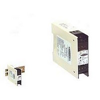
... SW36 5.2 mm (0.2") Figure 5a.SI-MAG3SM Sensor dimensions 75.0 mm (2.95") ! 22.5 mm (0.89") Figure 6. SI-MAG1C Controller dimensions Banner Engineering Corp., 9714 Tenth Ave. No., Minneapolis, MN 55441 • Phone: 763.544.3164 • Toll-free: 888.373.6767 • www.bannerengineering.com Magnet Style 78 mm Sensing (3.1") Surface (3.5") (2.7") 2 ...