CMRA2435-10 Crydom Co., CMRA2435-10 Datasheet - Page 2
CMRA2435-10
Manufacturer Part Number
CMRA2435-10
Description
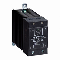
IC,Normally-Open Panel-Mount Solid-State Relay,1-CHANNEL,M:HL089HD4.3
Manufacturer
Crydom Co.
Series
CMRA24r
Specifications of CMRA2435-10
Circuit
SPST-NO (1 Form A)
Output Type
AC
Load Current
35A
Voltage - Input
90 ~ 140VAC
Voltage - Load
24 ~ 280 V
Mounting Type
DIN Rail
Termination Style
Screw Terminal
Package / Case
SSR with Integrated Heatsink
Lead Free Status / RoHS Status
Lead free / RoHS Compliant
On-state Resistance
-
Lead Free Status / Rohs Status
Lead free / RoHS Compliant


CMRINST
Rev. 081508
PAGE 2 OF 3
PROTECTION
Over Current and Short Circuit
A solid state relay should be protected by a semiconductor fuse.
This type of fuse provides extremely fast opening of the circuit.
A fuse should be selected that has an I t let-through rating that
is less than the I t capability of the SSR, for the same duration.
Transient Over Voltage (P OPTION)
Select "P" option for internal overvoltage protection. At the
presence of high voltage transient the output of the SSR will be
triggered on, and the transient will be passed on to the load circuit
This is a non-degrading method of protection that ensures that
other SSR benefits are maintained.
Earth Bonding (Grounding)
The CKR heatsink is equiped with an earth bonding screw as is
required for Class 1 Protection, in accordance with EN 60950
(VDE 0804).
Terminations
Wire Size
Connections
Recommended Screw Torque Range
ORDERING INFORMATION
Part Number
Package Style
Input (Control) Type
Output Voltage
Output Current
CMR = CMR Series
45
55
65
35
D
A
24 = 24 - 280
48 = 48 - 530
60 = 48 - 660
= 3-32 Vdc (CMRD24)
= 4-32 Vdc (CMRD48, CMRD60)
= 90-140 Vrms
= 18-36 Vrms (suffix E)
= 35 Amp
= 45 Amp
= 55 Amp
= 65 Amp
input and AWG#8 (4.8mm) output terminals.
minimum length of 0.4 inch (10 mm).
10-15 in lb (1.1-1.7 Nm) on output terminations.
• Maximum wire size of AWG#12 (2.5mm) on
• Ensure that wires ends are stripped to a
• 5-6 in lb (0.6-0.7 Nm) on input and
2
Vrms
Vrms
Vrms
2
CMR
A
2
4
Note: For detailed electrical specifications see Crydom individual data sheets.
3
5
E
P
MECHANICAL SPECIFICATIONS
1
0
(44.5)
(22.9)
(25.4)
(19.1)
OUTPUT
INPUT
1.75
0.75
© 2005 CRYDOM CORP, Specifications subject to change without notice.
1.0
.9
All dimensions are in inches (millimeters)
(63.5)
(109.2)
2.5
4.3
MOUNTING
HOLE/SLOT
0.17 (4.3) DIA.
(76.2)
3.0
Integrated Overvoltage Protection
(88.9)
Control Mode
AC Control Range
3.5
Blank = Zero Cross
Blank = Not Included
10
Blank = 90-140 Vrms
E
P
(76.2)
= Included
= Random
= 18-36 Vrms
3.0
HEAT SINK:
BLACK ANODIZED
ALUMINUM
Related parts for CMRA2435-10
Image
Part Number
Description
Manufacturer
Datasheet
Request
R

Part Number:
Description:
IC,Normally-Open Panel-Mount Solid-State Relay,1-CHANNEL,M:HL089HD4.3
Manufacturer:
Crydom Co.
Datasheet:
Part Number:
Description:
IC,Normally-Open Panel-Mount Solid-State Relay,1-CHANNEL,M:HL089HD4.3
Manufacturer:
Crydom Co.
Datasheet:
Part Number:
Description:
IC,Normally-Open Panel-Mount Solid-State Relay,1-CHANNEL,M:HL089HD4.3
Manufacturer:
Crydom Co.
Datasheet:

Part Number:
Description:
Relay; SSR; Zero-Switching; SPST-NO; Cur-Rtg 35A; Ctrl-V 90-140AC; Vol-Rtg 24-280AC
Manufacturer:
Crydom Company
Datasheet:
Part Number:
Description:
Relay; SSR; Zero-Switching; SPST-NO; Cur-Rtg 45A; Ctrl-V 90-140AC; Vol-Rtg 48-530AC
Manufacturer:
Crydom Company
Datasheet:
Part Number:
Description:
Relay; SSR; Zero-Switching; SPST-NO; Cur-Rtg 35A; Ctrl-V 90-140AC; Vol-Rtg 48-530AC
Manufacturer:
Crydom Company
Datasheet:
Part Number:
Description:
Relay; SSR; Zero-Switching; SPST-NO; Cur-Rtg 45A; Ctrl-V 90-140AC; Vol-Rtg 24-280AC
Manufacturer:
Crydom Company
Datasheet:
Part Number:
Description:
Relay; SSR; Zero-Switching; SPST-NO; Cur-Rtg 55A; Ctrl-V 90-140AC; Vol-Rtg 48-530AC
Manufacturer:
Crydom Company
Datasheet:

Part Number:
Description:
RELAY SSR 10-35MA INPUT 16 DIP
Manufacturer:
Crydom Co.
Datasheet:
Part Number:
Description:
RELAY SSR 3.5-10VDC INPUT 16 DIP
Manufacturer:
Crydom Co.
Datasheet:

Part Number:
Description:
RELAY SSR 5A 480VAC SIP
Manufacturer:
Crydom Co.
Datasheet:

Part Number:
Description:
RELAY SSR 12A 240VAC DC
Manufacturer:
Crydom Co.
Datasheet:

Part Number:
Description:
RELAY SSR 25A 240VAC DC
Manufacturer:
Crydom Co.
Datasheet:

Part Number:
Description:
POWER CONTROL SSR 15A DC IN
Manufacturer:
Crydom Co.
Datasheet:
Part Number:
Description:
RELAY SSR 125A 480VAC DC INPUT
Manufacturer:
Crydom Co.
Datasheet: