84-8512.5640 EAO, 84-8512.5640 Datasheet - Page 5
84-8512.5640
Manufacturer Part Number
84-8512.5640
Description
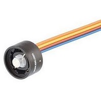
SWITCHING ELEMENT, 1NO, 3A, CABLE
Manufacturer
EAO
Datasheet
1.84-8512.5640.pdf
(8 pages)
Specifications of 84-8512.5640
No. Of Poles
1
Contact Current Max
3A
Contact Voltage Ac Max
240V
Switch Terminals
Cable
Circuitry
1NO
For Use With
84 Series Emergency Stop Switches
Lead Free Status / RoHS Status
Lead free / RoHS Compliant


Series 84
Shock resistance
(semi-sinusoidal)
max. 150 m/s
EN IEC 60068-2-27
Vibration resistance
(sinusoidal)
max. 100 m/s
EN IEC 60068-2-6/Fc
Climate resistance
Damp heat, cyclic :
96 hours, +25°C / 97% +55°C / 93% relative humidity,
as per EN IEC 60068-2-30
Damp heat, steady:
58 days, +40°C / 93% relative humidity,
as per EN IEC 60068-2-78
Dry heat:
96 hours, +70°C as per EN IEC 60068-2-2
Low temperature:
96 hours, -40°C as per EN IEC 60068-2-1
Saline mist:
96 hours, +35°C in chemical solution NaCI,
as per EN IEC 60068-2-11
Approvals
CE Declaration of Conformity
UL
SEV
Indicator / Iluminted Pushbutton
Switching element
Switching system
Short-travel switching system with 2 independent contact points
and tactile operation.
Guarantees reliable switching even of very light loads.
Fitted with 1 normally open contact
Material
Connection cable
Polyvinylchlorid (PVC), short-time heat-resistant up to 105°C
Material of contacts
Silver alloy gold plated
Switching element
Thermoplastic polyester (PET, PBT), as per UL94 V0 and
Polyacetale (POM), as per UL94 HB
Mechanical characteristics
Terminals
Plug-in/soldering terminals 2.8 x 0.8 mm (solderable)
Flat ribbon cable 0.5
PCB terminal
Actuating force
4.0 N ±0.2 N (measured at the lens)
Actuating travel
~0.5 mm
www.eao.com
2
2
, pulse width 11 ms, 3-axis, as per
at 10 Hz...500 Hz, 10 cycles, 3-axis, as per
104
2
mm
2
Rebound time
1 ms
Resistance to heat of soldering
260 °C, 5 s (PCB assembly)
350 °C, 10 s (when using a soldering iron)
as per EN IEC 60068-2-20
Mechanical life
Electrical characteristics
Illumination
Single-Chip or Multi-Chip LED, green, orange, red, yellow, blue and white
Operation voltage:
Current consumption: 40 mA
Contact resistance
Starting value (initial): 100 m , as per DIN IEC 60512-2
Isolation resistance
Electrical life
as per EN IEC 60512-5
5 million Cycles of operation 24 VAC, 50 mA at 480
5 million Cycles of operation 24 VAC, 100 mA at 240
2 million Cycles of operation 42 VAC, 50 mA at 840
2 million Cycles of operation 42 VAC, 100 mA at 420
300.000 Cycles of operation 42 VAC, 100 mA at cos
250.000 Cycles of operation 42 VAC, 200 mA at cos
1 million Cycles of operation 12 VDC, 250 mA at 48
1 million Cycles of operation 24 VDC, 50 mA at 480
1 million Cycles of operation 24 VDC, 100 mA at 240
5 million Cycles of operation 42 VDC, 25 mA at 1680
1.5 million Cycles of operation 42 VDC, 50 mA at 840
100.000 Cycles of operation 42 VDC, 100 mA at 420
500.000 Cycles of operation 24 VDC, 200 mA at L/R=30 ms
300.000 Cycles of operation 42 VDC, 100 mA at L/R=30 ms
100.000 Cycles of operation 42 VDC, 200 mA at L/R=30 ms
Switch rating
Voltage: 50 mVAC/DC ... 42 VAC/DC
Current: 10 μA...100 mA
Power: max. 2 W
Electric strength
500 VAC, 50 Hz, 1 min, as per DIN IEC 60512-2
Environmental conditions
Storage temperature
-40 °C ... +85 °C
Operating temperature
-25 °C ... +70 °C
Protection degree
IP 67 or IP 40, as per IEC 60529
Shock resistance
(semi-sinusoidal)
max. 100 m/s
as per EN IEC 60068-2-27/Ea
1 million cycles of operations
1 G
between all terminals at 100 VDC, as per DIN IEC 60512-2
2
, pulse width 11 ms, 3-axis,
12 VDC
Technical Data
24 VDC
20 mA
o
o
0,4
0,395
Related parts for 84-8512.5640
Image
Part Number
Description
Manufacturer
Datasheet
Request
R

Part Number:
Description:
Cap Film 260uF 400VDC PP 10% 84 X 51mm Screw Terminal Can Bulk
Manufacturer:
Kemet
Datasheet:

Part Number:
Description:
Indicator
Manufacturer:
EAO
Datasheet:


Part Number:
Description:
Switch Actuator
Manufacturer:
EAO
Datasheet:

Part Number:
Description:
Switch Actuator
Manufacturer:
EAO
Datasheet:
Part Number:
Description:
Switch Actuator
Manufacturer:
EAO
Datasheet:

Part Number:
Description:
INDICATOR, ALUMINUM
Manufacturer:
EAO
Datasheet:

Part Number:
Description:
SINGLE CHIP LED/ T1 BI-PIN/ 2.1VDC/20MA - RED
Manufacturer:
EAO
Datasheet:

Part Number:
Description:
INDICATOR, INCAND LAMP, BI PIN
Manufacturer:
EAO
Datasheet:

Part Number:
Description:
INDICATOR, BI-PIN
Manufacturer:
EAO
Datasheet:

Part Number:
Description:
INDICATOR, INCAND LAMP, MIDGET GROOVED
Manufacturer:
EAO
Datasheet: