LT4HW-AC240V PANASONIC EW, LT4HW-AC240V Datasheet - Page 7
LT4HW-AC240V
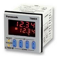
Manufacturer Part Number
LT4HW-AC240V
Description
TIMER, TWIN, 11 PINS, 240VAC
Manufacturer
PANASONIC EW
Datasheet
1.LT4HW-AC240VS.pdf
(7 pages)
Specifications of LT4HW-AC240V
Contact Configuration
SPDT
Nom Input Voltage
240V
Delay Time Range
99.99s To 9999h
Adjustment Type
Pushbutton
Relay Mounting
Panel
Svhc
No SVHC (15-Dec-2010)
External Depth
65mm
External Length /
RoHS Compliant


4) The input signal is applied by the
shorting of each input terminal with the
common terminal (terminal Q for 8-pin
types, terminal E for 11-pin types and
terminal
types). Never connect other terminals or
voltages higher than DC 40 V, because it
may destroy the internal circuitry.
5) Transistor output
(1) Since the transistor output is insulat-
Note: With the 8-pin type, there is no diode
(2) Use the diode connected to the out-
put transistor’s collector for absorbing
the reverse voltage from induced loads.
6) When wiring, use shielded wires or
metallic wire tubes, and keep the wire
lengths as short as possible.
7) For the load of the controlled output,
make sure that it is lower than the rated
control capacity.
5. Self-diagnosis function
If a malfunction occurs, one of the following displays will appear.
Note: Includes the possibility that the EEPROM’s life has expired.
50
Diode rating:
I
V
F
As NPN output
As PNP output
R
(forward current): 1 A
ed from the internal circuitry by a pho-
tocoupler, it can be used as an NPN
output or PNP (equal value) output.
(The above example is 11-pin type)
(reverse voltage): 600 V
between points I and O.
Display
6
for screw-down terminal
Load’s power supply
Load’s power supply
{
LT4H timer
{
LT4H timer
LT4H timer
Load
power supply
Malfunctioning CPU.
Malfunctioning memory. See
note.
Load’s
O
Load
O
I
I
Inductive load
Contents
8) Turning on and off the power supply
while operating in A2* (Power on delay)
or G (Totalizing On delay) will result in a
timer error to be generated due to the
characteristics of the internal circuitry.
Therefore, use the signal input or stop
input.
* Not related to the signal input.
9) When controlling the timer by turning
on the power supply, use only A (Power
on delay 1) or A2 (Power on delay 2).
Use of other modes in this situation will
result in timer errors. When using the
other modes, control the timer with the
signal input or stop input.
10) The operation mode and time range
can be set with the DIP switches on the
side of the timer. Make the DIP switch
settings before installing the timer on the
panel.
4. Conditions of usage
1) Avoid locations subject to flammable
or corrosive gases, excessive dust, oil,
vibrations, or excessive shocks.
2) Since the cover of the unit is made of
polycarbonate resin, avoid contact with
or use in environments containing methyl
alcohol, benzene, thinners, and other
organic solvents; and ammonia, caustic
sodas, and other alkaline substances.
3) If power supply surges exceed the val-
ues given below, the internal circuits may
become damaged. Be sure to use surge
absorbing element to prevent this from
happening.
• Surge wave form
[± (1.2 × 50) µs uni-polar full wave voltage]
Operating voltage Surge voltage (peak value)
24V AC type
100
AC type
DC type
90
50
30
0
Output condition
0
OFF
1.2
Time (µs)
Peak value
02/2003
6,000V
1,000V
Enter reset, RESET key,
or restart unit.
Restoration procedure
50
4) Regarding external noise, the values
below are considered the noise-resistant
voltages. If voltages rise above these
values, malfunctions or damage to the
internal circuitry may result, so take the
necessary precautions.
Noise wave form (noise simulator)
Rise time: 1 ns
Pulse width: 1 µs, 50 ns
Polarity: ±
Cycle: 100 cycles/second
5) When connecting the operation power
supply, make sure that no leakage cur-
rent enters the counter. For example,
when performing contact protection, if
set up like that of diagram A, leaking cur-
rent will pass through C and R, enter the
unit, and cause incorrect operation.
Diagram B shows the correct setup.
6) Long periods of continuous operation
in the count-up completed condition (one
month or more) will result in the weakening
of the internal electrical components
from the generated heat and, therefore,
should be avoided. If you do plan to use
the unit for such continuous operation,
use in conjunction with a relay as shown
in the circuit in the diagram below.
Operation power supply
Operation power supply
voltage
Noise
R
The values at start-up before the CPU
malfunction occurred.
R
Relay
Power supply terminals
Preset values after restoration
AC type
1,500V
T
Leakage current
R
T
24V AC type
(Fig. B)
(Fig. A)
Timer
R
DC type
1,000V
0
C
R
C
Receive output
from contact
at relay R
R
terminals
600V
Input
T
T
Related parts for LT4HW-AC240V
Image
Part Number
Description
Manufacturer
Datasheet
Request
R

Part Number:
Description:
TIMER DIGITAL 24VDC SCREW TERM
Manufacturer:
Panasonic Electric Works
Datasheet:

Part Number:
Description:
TIMER, TWIN, SCREW, 240VAC
Manufacturer:
PANASONIC EW
Datasheet:
Part Number:
Description:
TIMER, TWIN, 11 PINS, 24VDC
Manufacturer:
PANASONIC EW
Datasheet:
Part Number:
Description:
Manufacturer:
Panasonic Electric Works
Datasheet:
Part Number:
Description:
Manufacturer:
Panasonic Electric Works
Datasheet:

Part Number:
Description:
POWER RELAY, 24VDC, 30A, SPST-NO
Manufacturer:
PANASONIC EW
Datasheet:

Part Number:
Description:
POWER RELAY, SPDT, 12VDC, 10A, PC BOARD
Manufacturer:
PANASONIC EW

Part Number:
Description:
POWER RELAY, 24VDC, 5A, SPST-NO, PCB
Manufacturer:
PANASONIC EW
Datasheet:


Part Number:
Description:
SIGNAL RELAY, DPDT, 4.5VDC, 1A, SMD
Manufacturer:
PANASONIC EW
Datasheet:

Part Number:
Description:
SIGNAL RELAY, DPDT, 5VDC, 2A, PC BOARD
Manufacturer:
PANASONIC EW
Datasheet:


Part Number:
Description:
PHOTOMOS RELAY, 60VDC, 400mA
Manufacturer:
PANASONIC EW
Datasheet:

Part Number:
Description:
PHOTOMOS RELAY, 400V, 150mA
Manufacturer:
PANASONIC EW
Datasheet: