HE2AN24 PANASONIC EW, HE2AN24 Datasheet
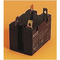
HE2AN24
Specifications of HE2AN24


Related parts for HE2AN24


HE2AN24 Summary of contents
Page 1
SPECIFICATIONS Contacts Type DC coil type Arrangement 1a Contact material Initial contact resistance, max. (By voltage drop 1A Nominal 277 V switching capacity AC Max. switching 8,310 ...
Page 2
HE TYPES Contact arrangement Terminal shape 1 Form A HE1aN-DC6V HE1aN-DC12V Plug-in terminal HE1aN-DC24V HE1aN-DC48V HE1aN-DC110V HE1aN-S-DC6V HE1aN-S-DC12V Screw terminal HE1aN-S-DC24V HE1aN-S-DC48V HE1aN-S-DC110V HE1aN-SW-DC6V HE1aN-SW-DC12V DC Screw terminal HE1aN-SW-DC24V type (wide pitch) HE1aN-SW-DC48V HE1aN-SW-DC110V HE1aN-Q-DC6V HE1aN-Q-DC12V NEMA terminal HE1aN-Q-DC24V HE1aN-Q-DC48V ...
Page 3
DIMENSIONS 1. Plug-in terminal type 1a 36.4 2-4.5 dia. 1.433 2-.177 dia 1.575 50 8.4 10.25 1.969 .331 .404 FASTON No. 250 0.8 6.35 .031 .250 3.5 .138 2. NEMA terminal type 1a 47.6 1.874 36.4 ...
Page 4
HE 4. Screw terminal type (wide pitch) 1a 51.0 2.008 47.6 1.874 40.0 1.575 M4.5 14.4 .567 4.5 .177 33.5 M3.5 1.319 50.0 1.969 60 2.362 3.5 .138 5. PC board terminal type 38.0 33 1.496 1.299 36.3 1.429 0.5 ...
Page 5
Form A Type 1. Maximum switching power 100 50 AC resistive resistive 5 1 0.5 30 100 500 1,000 Contact voltage Ambient temperature characteristics Sample: HE2aN-AC120V, 6 pcs Pick- ...
Page 6
HE HE RELAY ACCESSORIES Terminal socket instantly attachable to DIN rail DIMENSIONS 1 Form A, 2 Form .354 11 2 .433 22 14.4 60 .866 .567 2.362 .433 9 .354 4 5 ...