G6CK-2117P-US 12DC Omron, G6CK-2117P-US 12DC Datasheet - Page 3
G6CK-2117P-US 12DC
Manufacturer Part Number
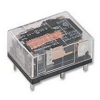
G6CK-2117P-US 12DC
Description
RELAY, PCB, SPNO & SPNC, 12VDC
Manufacturer
Omron
Datasheet
1.G6CK-1117P-US_5DC.pdf
(9 pages)
Specifications of G6CK-2117P-US 12DC
Relay Type
Power
Coil Voltage Vdc Nom
12V
Contact Current Max
8A
Contact Voltage Ac Nom
250V
Contact Voltage Dc Nom
30V
Coil Resistance
514ohm
Coil Type
DC Coil
Coil Current
23.3mA
Nom
RoHS Compliant
Contact Configuration
SPST-1NO / 1NC
Rohs Compliant
Yes


G6C
Double-winding Latching Type
Note:
■
Note:
■
198
Rated voltage
Set coil
Reset coil
Must set voltage
Must reset voltage
Max. voltage
Power consumption
Load
Rated load
Contact material
Rated carry current
Max. switching voltage
Max. switching current
Max. switching power
Failure rate (reference value)
Contact resistance
Operate (set) time
Release (reset) time
Bounce time
Min. set/reset signal width
Max. switching frequency
Insulation resistance
Dielectric strength
Impulse withstand voltage
Vibration resistance
Shock resistance
Ambient temperature
Ambient humidity
Endurance
Weight
Contact Ratings
Characteristics
1. The rated current and coil resistance are measured at a coil temperature of 23°C with a tolerance of ±10%.
2. Operating characteristics are measured at a coil temperature of 23°C.
3. The minimum pulse width of the set and reset voltage is 20 ms.
P level: λ 60 = 0.1 x 10
Item
Rated current
Coil resistance
Coil inductance
(H) (ref. value)
Rated current
Coil resistance
Coil inductance
(H) (ref. value)
–6
operations
Resistive load
(cos φ = 1)
10 A at 250 VAC;
10A at 30 VDC
Ag Alloy (Cd free)
10 A
380 VAC, 125 VDC (the case of latching 250 VAC, 125 VDC)
10 A
2,500 VA, 300 W
10 mA at 5 VDC
Armature OFF
Armature ON
Armature OFF
Armature ON
30 m Ω max.
10 ms max. (mean value: approx. 5 ms)
10 ms max. (mean value: approx. 2 ms; latching types: mean value: approx. 5 ms)
Operate: 5 ms max.
Release: 5 ms max.
Latching type: 20 ms (at 23°C)
Mechanical: 18,000 operations/hr
Electrical:
1,000 M Ω min. (at 500 VDC, at 250 VDC between set coil and reset coil)
2,000 VAC, 50/60 Hz for 1 min between coil and contacts
2,000 VAC, 50/60 Hz for 1 min between contacts of different polarity
1,000 VAC, 50/60 Hz for 1 min between contacts of same polarity
250 VAC, 50/60 Hz for 1 min between set and reset coils (double winding latching type)
6.000 V (1.2 x 50 µs) between coil and contacts (latching types: 4,500 V, 1.2 50 µs)
Destruction: 10 to 55 to 10 Hz, 0.75-mm single amplitude (1.5-mm double amplitude)
Malfunction: 10 to 55 to 10 Hz, 0.75-mm single amplitude (1.5-mm double amplitude)
Destruction: 1,000 m/s
Malfunction: 100 m/s
Operating: − 25°C to 70°C (with no icing)
Operating: 5% to 85%
Mechanical: 50,000,000 operations min. (at 18,000 operations/hr)
Electrical:
Approx. 5.6 g
1,800 operations/hr (under rated load)
3 VDC
93.5 mA
32.1 Ω
0.03
0.02
93.5 mA
32.1 Ω
0.03
0.02
70% max. of rated voltage
70% min. of rated voltage
130% of rated voltage (at 23 ° C)
Set coil:
Reset coil: Approx. 280 mW
100,000 operations min. (at 1,800 operations/hr)
SPST-NO
Inductive load
(cos φ = 0.4; L/R = 7 ms)
5 A at 250 VAC;
5 A at 30 VDC
1,250 VA, 220 W
2
2
Approx. 280 mW
5 VDC
56.0 mA
89.3 Ω
0.07
0.06
56.0 mA
89.3 Ω
0.08
0.07
Resistive load
(cos φ = 1)
8 A at 250 VAC;
8A at 30 VDC
8 A
8 A
2,000 VA, 240 W
6 VDC
46.7 mA
129 Ω
0.10
0.08
46.7 mA
129 Ω
0.12
0.10
SPST-NO+SPST-NC
12 VDC
23.3 mA
514 Ω
0.37
0.32
23.3 mA
514 Ω
0.47
0.38
875 VA, 170 W
Inductive load
(cos φ = 0.4; L/R = 7 ms)
3.5 A at 250 VAC;
3.5 A at 30 VDC
24 VDC
11.7 mA
2,056 Ω
1.56
1.18
11.7 mA
2,056 Ω
1.46
1.13
G6C
Related parts for G6CK-2117P-US 12DC
Image
Part Number
Description
Manufacturer
Datasheet
Request
R

Part Number:
Description:
POWER PCB RELAY
Manufacturer:
Omron
Datasheet:
Part Number:
Description:
POWER PCB RELAY
Manufacturer:
Omron
Datasheet:
Part Number:
Description:
RELAYS
Manufacturer:
Omron
Datasheet:
Part Number:
Description:
POWER PCB RELAY
Manufacturer:
Omron
Datasheet:
Part Number:
Description:
POWER PCB RELAY
Manufacturer:
Omron
Datasheet:

Part Number:
Description:
G6S-2GLow Signal Relay
Manufacturer:
Omron Corporation
Datasheet:
Part Number:
Description:
Compact, Low-cost, SSR Switching 5 to 20 A
Manufacturer:
Omron Corporation
Datasheet:
Part Number:
Description:
Manufacturer:
Omron Corporation
Datasheet:
Part Number:
Description:
Manufacturer:
Omron Corporation
Datasheet:
Part Number:
Description:
Manufacturer:
Omron Corporation
Datasheet:
Part Number:
Description:
Manufacturer:
Omron Corporation
Datasheet: