A6E-7101 Omron, A6E-7101 Datasheet
A6E-7101
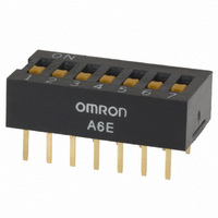
Specifications of A6E-7101
A6E7101
SW908


Related parts for A6E-7101


A6E-7101 Summary of contents
Page 1
... A6E-2101 3 52 A6E-3101 4 40 A6E-4101 5 33 A6E-5101 6 28 A6E-6101 7 24 A6E-7101 8 21 A6E-8101 9 19 A6E-9101 10 17 A6E-0101 Specifications Ratings/Characteristics ■ Switching capacity VDC (minimum current) at 3.5 VDC Operating: –20 ° ° C (with no icing) Ambient temperature Ambient humidity Operating: 35% to 90% 100 M W min ...
Page 2
... Raised Actuator with DIP Terminal A6E-@104 No. of poles Model 2 A6E-2101 A6E-2104 3 A6E-3101 A6E-3104 4 A6E-4101 A6E-4104 5 A6E-5101 A6E-5104 6 A6E-6101 A6E-6104 7 A6E-7101 A6E-7104 8 A6E-8101 A6E-8104 9 A6E-9101 A6E-9104 10 A6E-0101 A6E-0104 Flat Actuator P: Pole numbers PCB Dimensions (Top View) Dimension A 6.64 9.18 11.72 14.26 16.80 19 ...
Page 3
... A6ER-2104 3 A6ER-3101 A6ER-3104 4 A6ER-4101 A6ER-4104 5 A6ER-5101 A6ER-5104 6 A6ER-6101 A6ER-6104 7 A6ER-7101 A6ER-7104 8 A6ER-8101 A6ER-8104 9 A6ER-9101 A6ER-9104 10 A6ER-0101 A6ER-0104 Installation Internal Connections (Top View) ■ Precautions Be sure to refer to General Precautions on pages for details on proper use. ALL DIMENSIONS SHOWN ARE IN MILLIMETERS. To convert millimeters into inches, multiply by 0.03937. To convert grams into ounces, multiply by 0.03527. ...
Page 4
... General Precautions for Soldering Make sure that the striker of slide-type DIP Switches is set fully to either ON or OFF. (For A6E and A6ER models, however, set the Switch to OFF before soldering.) Make sure that Rotary DIP Switches are correctly set to 0. Misalignment may result in reduced sensitivity due to the soldering heat ...
Page 5
... A6A, A6C, A6CV, A6D, A6DR, A6T (with seal tape), A6S-H (with seal tape), A6H (with seal tape) Non-washable A6R, A6RV, A6T (standard/raised actuator), A6S- H (standard/raised actuator), A6E, A6ER 2. Washing Procedure Ultrasonic cleaning is not available for slide-type DIP Switches with seal tape. These models may be wiped or dipped into wash- ing agents for one minute maximum ...
Page 6
... A −0.2 note.) Note: The perforations along both sides are for Switch- es with 7 poles or more. The perforations on the bottom of the diagram are not provided on Switches with 6 poles or less. 13 dia. 330 Label Applicable A6S-@102-PH Applicable models models Standard Conforms to Standard JEITA ...