71BF30-08-2-06N Grayhill Inc, 71BF30-08-2-06N Datasheet - Page 4
71BF30-08-2-06N
Manufacturer Part Number
71BF30-08-2-06N
Description
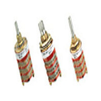
Rotary Switch, 1/4" Shaft, PC Mount, 30°
Manufacturer
Grayhill Inc
Series
71r
Datasheet
1.71BF30-08-2-06N.pdf
(14 pages)
Specifications of 71BF30-08-2-06N
Number Of Positions
6
Number Of Decks
8
Number Of Poles Per Deck
2
Circuit Per Deck
DP6T
Contact Rating @ Voltage
0.25A @ 28VDC
Actuator Type
Flatted (6.35mm dia)
Mounting Type
Panel, PCB Through Hole
Termination Style
PC Pin
Orientation
Right Angle
Angle Of Throw
30°
Total # Of Positions
6
Pole Throw Configuration
DP
Actuator Style
Shaft
Actuator Material
Stainless Steel
Current Rating (max)
0.25A
Illumination Type
Not Required
Ac Voltage Rating (max)
115VVAC
Dc Voltage Rating (max)
30VVDC
Contact Material
Silver Alloy/Beryllium Copper
Product Height (mm)
18.7mm
Product Depth (mm)
82.85mm
Product Length (mm)
22.23mm
Mounting Style
Panel Mount/Through Hole
Terminal Type
PC Pins
Lead Free Status / RoHS Status
Vendor undefined / Vendor undefined
Lead Free Status / RoHS Status
Vendor undefined / Vendor undefined
Other names
Q5439640A


DIMENSIONS: Metric
CIRCUIT DIAGRAMS: Standard, Military and Metric PC Mount
Grayhill, Inc. • 561 Hillgrove Avenue • LaGrange, Illinois
4mm Diameter Shaft: Style EF and ESF
30° Angle
of Throw
Grayhill part number and date code marked on detent cover label. Customer part number marked on request.
22,23 ± 0,4
0,51 ± 0,08 TYP.
Ø 17,45
± 0,4
No. of
Decks
1
2
3
4
5
6
ONE POLE
TWO POLE
6,00 + 0,00 –0,08
19,33
24,87
30,40
35,94
41,48
54,13
Dim.
A
TERMINAL
NO. 1
12
12
C
BUSHING
FLATS
L
All dimensions are in millimeters
11
11
OF
Dim.
0,79
0,79
0,79
0,79
0,79
7,92
10 9 8 7 6 5 4 3
C2
10 9 8 7 6 5 4 3 2 1
B
Ø 4,00 ± 0,03
Approx.
Circuit is Viewed From Shaft End and Shown in Position No. 1
Weight
Grams
12
14
16
18
20
22
C1
8,00 ± 0,3
Decks
No. of
2
C1
10
11
12
7
8
9
C
1
C L
25,00 ± 0,51
L
60525-5997 • USA • Phone: 708-354-1040 • Fax: 708-354-2820 • www.grayhill.com
M7 X 0,75
THREAD
OF BUSHING
KEYWAY OR
FLATS
10,46 ± 0,25
59,66
65,20
70,74
76,28
81,81
87,35
Dim.
A
Dim.
7,92
7,92
7,92
7,92
7,92
7,92
.0,38
± 0,03
TYP.
B
Note: Common location for a single pole per
STUD PROJECTION
C
L
(SEE CHARACTER-
deck switch. For common location on
two pole switches see circuit diagrams.
DIM. A ± 1,17
C
Approx.
L
Weight
Grams
36° Angle
of Throw
Multi-Deck Rotary Switches
24
26
28
30
32
34
C
L
DIM. B REF.
2,79 ± 0,25
TYP.
ISTICS)
SEE NOTE
BELOW
ONE POLE
TWO POLE
14,27
± 0,38
10 9 8 7 6 5 4 3 2 1
10 9 8 7 6 5 4 3 2 1
3,96 ± 0,25
3,96 ± 0,25
C2
18,42
± 0,04
TYP.
TYP.
SEE
NOTE
30° and 36° Angle of Throw may be
interposed on either shaft diameter.
SEE
NOTE
36° Angle of Throw
30° Angle of Throw
Rear Views
C
C L
L
Ø 12,7
± 0,38
Ø 12,7
± 0,38
C
L
C L
C L
C1
C1
C L
C L
C L
C L
C L
3,18 ± 0,25
OF BUSHING
KEYWAY OR
FLATS
3,18 ± 0,25
0,94 ± 0,13
TYP.
0,94 ± 0,13
TYP.
1,91 ± 0,13
TYP.
1,91 ± 0,13
TYP.
7,62 ± 0,25
7,62 ± 0,25
TYP.
TYP.
9,35
REF.
REF.
9,35
Rotary
5
Related parts for 71BF30-08-2-06N
Image
Part Number
Description
Manufacturer
Datasheet
Request
R

Part Number:
Description:
Rotary Switch, 1/4" Shaft, PC Mount, 30°
Manufacturer:
Grayhill Inc

Part Number:
Description:
Rotary Switch, 1/4" Shaft, PC Mount, 30°
Manufacturer:
Grayhill Inc
Datasheet:
Part Number:
Description:
Rotary Switch, 1/4" Shaft, PC Mount, 30°
Manufacturer:
Grayhill Inc
Part Number:
Description:
Rotary Switch, 1/4" Shaft, PC Mount, 30°
Manufacturer:
Grayhill Inc
Part Number:
Description:
Rotary Switch, 1/4" Shaft, PC Mount, 30°
Manufacturer:
Grayhill Inc
Part Number:
Description:
Rotary Switch, 1/4" Shaft, PC Mount, 30°
Manufacturer:
Grayhill Inc
Part Number:
Description:
Rotary Switch, 1/4" Shaft, PC Mount, 30°
Manufacturer:
Grayhill Inc
Datasheet:
Part Number:
Description:
71BF30-01-1-12S-C Mount, 30°
Manufacturer:
Grayhill Inc
Datasheet:
Part Number:
Description:
Rotary Switch, 1/4" Shaft, PC Mount, 30°
Manufacturer:
Grayhill Inc