600-3140-00 EAO, 600-3140-00 Datasheet
600-3140-00
Specifications of 600-3140-00


Related parts for 600-3140-00


600-3140-00 Summary of contents
Page 1
... Switches and Indicators Swisstac ...
Page 2
... Switches and Indicators Index Series Swisstac Description Product Assembly Mounting Instruction Product Range Technical Data Drawing / Dimension / Layouts Circuit Drawing Marking 582 01.2000 - pushbuttons for standard mounting - pushbuttons for flush mounting - accessories / spare parts Page 583 Page 584 Page 585 Page 591 ...
Page 3
... Ideal for switch interlock systems SWISSTAC switches can be mechanically combined in many ways to form switch interlock systems and in fact in rows switches. This means that complicated protection and relay interlocks are unnecessa- ry. Individual and irregular spacings between the switches of an array are no problem either ...
Page 4
product assembly illuminated-/pushbutton 0 pushbutton-/illuminated pushbutton for flush mounting 0 584 01.2002 1 lens 2 front bezel 3 fixing nut 4 spring with pin for changing from maintained to momentary 5 intermediate section 6 holder for switching element 7 switching ...
Page 5
Mounting Instruction illuminated-/pushbutton 35mm The switch is mounted in a fascia or control panel in three steps: 1. Detach terminal block as in drawing, remove fixing nut 2. Insert switch from the front in fascia/control panel 3. Reassemble the switch ...
Page 6
Mounting Instruction indicator The indicator is mounted in a fascia/control panel in two steps: 1. Insert indicator from back side in fascia/control panel 2. Snap on bezel and tighten fixing nut 2 Lens Bezel indicator 30 ...
Page 7
Mounting Instruction emergency stop switch with key release The switch is mounted in a fascia or control panel in three steps: 1. Detach front section, just in released position drawing, remove fixing nut 2. ...
Page 8
Mounting Instruction keylock switch 55 mm The switch is mounted in a fascia/control panel in three steps: 1. Remove front section as in drawing 2. Insert switch from back side in fascia/control panel 3. Snap on front section (see Note) ...
Page 9
Mounting Instruction selector switch 55 mm The switch is mounted in a fascia/control panel in three steps: 1. Remove front section as in drawing 2. Insert switch from back side in fascia/control panel 3. Snap on front section (see Note) ...
Page 10
Mounting Instruction buzzer The alarmbuzzer is mounted in a fascia/control panel in two steps: 1. Insert alarmbuzzer from backside in fascia/control panel 2. snap on bezel and tighten fixing nut buzzerelement bezel 590 01.2002 buzzerhousing Swisstac ...
Page 11
... Swisstac dia. Typ-Nr. Typ-Nr. Typ-Nr. 690-6000-00 690-4000-00 690-2000-00 690-6000-W0 690-4000-W0 690-2000-W0 lamp socket part no 3/4 990-.000- 5.5 890-.000- 3/4 990- ...
Page 12
... Typ-Nr. Typ-Nr 680-6000-00 680-4000-00 MA 600-6000-00 600-4000- 680-6000-W0 680-4000-W0 MA 600-6000-W0 600-4000-W0 Swisstac 18 mm dia. e Typ-Nr. 680-2000- 0,004 600-2000- 0,004 680-2000- 0,005 600-2000-W0 3 ...
Page 13
Pushbuttons for standard mounting illuminated-/pushbutton protection degree IP 40/ determined by front bezel and lens d lens page 623 d front bezel for illuminated-/pushbutton and indicator ...
Page 14
Pushbuttons for standard mounting emergency stop switch label for emergency stop switch page 636 unlocking emergency stop switch twist to release according to VDE max are permitted Continued on ...
Page 15
Pushbuttons for standard mounting unlocking emergency stop switch 55 - key to release 70 mm standard lock B2 390, other lock numbers on request according to VDE max are permitted contacts : 1 normally closed = 1 NC, ...
Page 16
Pushbuttons for standard mounting emergency stop switch foolproof 41 mm according to EN 418 d label for emergency stop switch page 636 unlocking emergency stop switch twist to release foolproof 41 mm standard lock 1001 key to release contacts : ...
Page 17
Pushbuttons for standard mounting pushbutton with mushroom-head cap mushroom-head cap page 625 d front bezel for mushroon-head pushbutton page 628 pushbutton with mushroom-head cap contacts : normally ...
Page 18
Pushbuttons for standard mounting keylock switch 2 positions front cap for keylock-/selector switch 2 positions page 625 maint. mom 90˚ 60˚ degree of protec- tion 0 keylock switch ...
Page 19
Pushbuttons for standard mounting maint. mom 90˚ 60˚ degree of protec- tion 0 keylock switch 2 positions standard lock B2 300, other lock numbers on re- quest Continued on next page key ...
Page 20
... Pushbuttons for standard mounting maint. mom 90˚ 60˚ degree of protec- tion 0 keylock switch positions standard lock B2 300, other lock numbers on re- quest Continued on next page 600 01.2002 key mounting removable depth A+C Swisstac e part no. ...
Page 21
Pushbuttons for standard mounting maint. mom 90˚ 60˚ degree of protec- tion 0 keylock switch 2 positions standard lock B2 300, other lock numbers on re- quest contacts : normally closed = ...
Page 22
Pushbuttons for standard mounting keylock switch 3 positions front cap for keylock-/selector switch 3 positions page 626 maint. mom 90˚ 60˚ degree of protection 0 keylock switch 3 positions ...
Page 23
Pushbuttons for standard mounting selector switch 2 positions front cap for keylock-/selector switch 2 positions page 625 d lever page 627 maint. mom 90˚ 60˚ degree of protection selector switch ...
Page 24
Pushbuttons for standard mounting maint. mom 90˚ 60˚ degree of protection selector switch 2 positions Continued on next page 604 01.2002 mounting depth part no ...
Page 25
Pushbuttons for standard mounting maint. mom 90˚ 60˚ degree of protection selector switch 2 positions contacts : normally closed = NC, normally open = NO switching action : maintained ...
Page 26
Pushbuttons for standard mounting selector switch 3 positions front cap for keylock-/selector switch 3 positions page 626 d lever page 627 maint. mom 90˚ 60˚ degree of pro- tection selector ...
Page 27
Pushbuttons for standard mounting buzzer buzzer element page 627 d front bezel for buzzer page 628 degree of protection buzzer connection method : soldering-/plug-in terminal ...
Page 28
... 3/4 circuit drawings from page 657, technical drawings from page 642, mounting dimensions from page 652 608 01.2002 degree of protection part no. part no 690-6000-00 690-4000- 690-6000-W0 690-4000-W0 Swisstac 25 mm dia. part no. e 690-2000- 0,004 690-2000- 0,005 ...
Page 29
Pushbuttons for Flush mounting indicator for flush mounting protection degree lens page 623 d front bezel for indicator page 627 d front bezel-set for flush mounting page 628 d ...
Page 30
... Typ-Nr. Typ-Nr. M 680-4000-00 680-6000-00 MA (M) 600-4000-00 600-6000-00 M 680-4000-W0 680-6000-W0 MA (M) 600-4000-W0 600-6000-W0 Swisstac 25 mm dia. e Typ-Nr. 680-2000- 0,004 0,004 0,004 600-2000- 0,004 0,004 0,004 680-2000-W0 ...
Page 31
Pushbuttons for Flush mounting pushbutton-/illuminated pushbutton for flush mounting protection degree lens page 623 d front bezel for illuminated-/pushbutton page 627 d front bezel-set for flush mounting page 628 ...
Page 32
Pushbuttons for Flush mounting keylock switch 2 positions for flush mounting front cap for keylock-/selector switch 2 positions page 625 d front bezel-set for flush mounting page 628 maint. mom 90˚ 60˚ C ...
Page 33
Pushbuttons for Flush mounting maint. mom 90˚ 60˚ degree of protection 0 keylock switch 2 positions IP 40 for flush mounting Continued on next page key remova- mounting depth ble ...
Page 34
Pushbuttons for Flush mounting maint. mom 90˚ 60˚ degree of protection 0 keylock switch 2 positions IP 65 for flush mounting Continued on next page 614 01.2002 key remova- mounting depth ble ...
Page 35
Pushbuttons for Flush mounting maint. mom 90˚ 60˚ degree of protection 0 keylock switch 2 positions IP 65 for flush mounting contacts : normally closed = NC, normally open = NO switching ...
Page 36
Pushbuttons for Flush mounting keylock switch with 3 positions for flush mounting front cap for keylock-/selector switch 3 positions 626 d front bezel-set for flush mounting page 628 maint. mom 90˚ 60˚ B ...
Page 37
Pushbuttons for Flush mounting selector switch 2 positions for flush mounting front cap for keylock-/selector switch 2 positions page 625 d lever page 627 d front bezel-set for flush mounting page 628 maint. mom. A ...
Page 38
Pushbuttons for Flush mounting maint. mom 90˚ 60˚ degree of protection selector switch 2 positions IP 65 for flush mounting Continued on next page 618 01.2002 mounting depth part no. 76 ...
Page 39
Pushbuttons for Flush mounting maint. mom 90˚ 60˚ degree of protection selector switch 2 positions IP 65 for flush mounting contacts : normally closed = NC, normally open = NO switching ...
Page 40
Pushbuttons for Flush mounting selector switch 3 positions for flush mounting front cap for keylock-/selector switch 3 positions page 626 d lever page 627 d front bezel-set for flush mounting page 628 maint. mom. A ...
Page 41
Pushbuttons for Flush mounting buzzer for flush mounting buzzer element page 627 d front bezel for buzzer page 628 d front bezel set for flush mounting for buzzer page 628 degree ...
Page 42
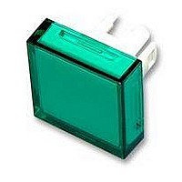
... Typ-Nr. Typ-Nr. Typ-Nr. blue 600-5150-00 600-3150-00 600-1150-00 yellow 600-5170-00 600-3170-00 600-1170-00 green 600-5140-00 600-3140-00 600-1140-00 orange 600-5110-00 600-3110-00 600-1110-00 red 600-5120-00 600-3120-00 600-1120-00 white 600-5160-00 600-3160-00 600-1160-00 blue 600-5250-00 600-3250-00 600-1250-00 yellow 600-5270-00 600-3270-00 600-1270-00 green 600-5240-00 ...
Page 43
plastic dia dia ...
Page 44
plastic (not re- commended for film insert dia dia dia. of ...
Page 45
... 0,002 200-4001-01 0,002 200-5001-01 0,002 200-6001-01 0,002 200-9001-01 0,002 200-0001-01 0,002 200-1001-01 0,002 200-2001-01 0,002 200-7001-01 0,002 200-8001-01 0,002 200-3004-00 0,002 200-4004-00 0,002 200-5004-00 0,002 200-6004-00 0,002 200-9004-00 0,002 200-0004-00 0,002 200-1004-00 0,002 200-2004-00 0,002 200-7004-00 0,002 200-8004-00 0,002 625 01.2002 ...
Page 46
... (90° grey 200-7002-03 (60°) black 200-8002- (60° grey 200-3002-04 (90°) black 200-4002- (60° grey 200-5002-04 (90°) black 200-6002- (60° grey 200-9002-04 (90°) black 200-0002- (60° grey 200-1002-04 (90°) black 200-2002- (60° grey 200-7002-04 (90°) black 200-8002-04 Swisstac ...
Page 47
... green 200-.245-00 red 200-.225-00 white 200-.265-00 front dimension material colour part no plastic grey 200-3000-00 black 200-4000- plastic grey 200-5000-00 black 200-6000- plastic grey 200-9000-00 black 200-0000- dia. plastic grey 200-1000-00 black 200-2000- dia. plastic grey 200-7000-00 black 200-8000-00 ...
Page 48
... Typ-Nr. Typ-Nr. plastic black 200-4400-V0 plastic black 200-6400-V0 plastic black degree of protection material colour IP 40 plastic black degree of protection Typ-Nr 200-6008- 200-6008-W0 Swisstac 18 mm dia. e Typ-Nr. 200-1000-00 0,002 200-2000-00 0,002 Typ-Nr. 200-9000-00 0,002 200-0000-00 0,002 18 mm dia. e Typ-Nr. 0,007 0,008 200-8400-V0 ...
Page 49
... Typ-Nr. Typ-Nr. Typ-Nr. 200-0008-W0 200-6008-00 200-4008- material colour Typ-Nr. Typ-Nr. plastic black 200-4408-V0 plastic black 200-6408-V0 ...
Page 50
... IP 65 630 01.2002 part no. 200-8009-W0 material part no. silicone 200-9009-W0 material part no. silicone 200-7009- dia. colour Typ-Nr. Typ-Nr. Typ-Nr. grey 200-5006-00 200-3006-00 200-1006-00 black 200-6006-00 200-4006-00 200-2006-00 black 200-6006-W0 200-4006-W0 200-2006-W0 Swisstac e 0,001 e 0,001 e 0,001 e 0,003 0,003 0,003 ...
Page 51
... Typ-Nr. Typ-Nr. Typ-Nr. 200-5006-00 200-3006-00 200-1006-00 200-6006-00 200-4006-00 200-2006-00 200-6006-W0 200-4006-W0 200-2006-W0 use for emergency stop switch foolproof with key to release for keylock switch for emergency stop switch with key to release part no 601-0000-00 P 601-0000- ...
Page 52
... blue technical drawings from page 642 632 01.2002 part no 600-0000-00 P 600-0000- 606-0000-00 P 606-0000- 607-0000-00 P 607-0000-0P part no. 202-0600-00 part no. 270-0000-00 270-0000-0P part no. 260-9000-00 260-8000-00 colour material of contacts part no. - gold plated 201-0500-00 grey - gold plated 201-0800-00 P gold plated 221-0800-0P green - ...
Page 53
accessories holder for 2 switching elements use holder for 2 switching elements push-pull illuminated switch for pushbutton 35 mm, keylock-/selector switch 45 mm holder for 3 switching elements use holder for 3 switching elements for illuminated-/pushbuttons 55-70 mm spring with ...
Page 54
3/4 filament lamp 3/4 filament lamp ...
Page 55
LED T 5.5 number of chips LED T 5.5 6 with built-in protective diode Note: For optimal illumination we stron- gly recommend using our new single-chip LEDs. For new designs, only the new single-chip LEDs should be cho- sen. ...
Page 56
accessories for emergency stop switch label for emergency stop switch label for emergency stop switch yellow, other constructions on request slow-make switching element for emergency stop switch slow-make switching element for emergen- cy stop switch technical drawings from page 642 ...
Page 57
... designs location strip anti-twisting, in-line arrays or single switches lens remover lens remover lamp/LED remover lamp/LED remover Warning: ...
Page 58
... Swisstac Protection class Front side IP 65 Switching element IP 40 Ambient temperature -25°C as per DIN EN 60068-2-1 +55°C as per DIN EN 60068-2-2 Storage temperature -40°C to +85°C Mechanical service life EMERGENCY button 50,000 operations Electrical characteristic values Switch rating Silver contact (Solder/plug-inmin. 20 VAC connection)max ...
Page 59
... Connection Brass gilded 2.8 x 0.5 mm solder/plug-in or PCB connection 1 mm² max. connection cross-section Mechanical characteristic values Ambient temperature -25°C as per DIN EN 60068-2-1 +55°C as per DIN EN 60068-2-2 Storage temperature -40°C to +85°C Mechanical service life 8000 switching cycles Contact opening width Swisstac > ...
Page 60
... UL 1054, VDE 0630 (EMERGENCY button VDE 0660), CSA 22.2. Mechanical characteristic values Resistance to vibration tested as per DIN EN 60068-2-6 ( 2000 Hz) Shock resistance tested as per DIN EN 60068-2-27 (semi-sinusoidal during 11 ms) (single impacts, semi-sinusoidal during per DIN EN 60068-2-29 Approvals - CE (declaration of conformity) - CSA ...
Page 61
... Mechanical characteristic values Ambient temperature -25°C to +55°C -25°C as per DIN EN 60068-2-1 +55°C as per DIN EN 60068-2-2 Storage temperature -40°C to +85°C as per DIN EN 60068 Mechanical service life switching cycles Contact opening width 2 x 0.65 mm Contact cleaning path ...
Page 62
drawings technical drawings 1 indicator actuator 35 mm, pushbutton-/illuminated pushbutton actuator 35 mm page 591, 592 2 indicator mm, buzzer page 591, 607 3 indicator page 591 4 indicator ...
Page 63
drawings 7 indicator page 591 8 illuminated-/pushbutton page 593 9 illuminated-/pushbutton page 593 10 illuminated-/pushbutton page 593 11 illuminated-/pushbutton page ...
Page 64
drawings 13 emergency stop switch page 594 14 emergency stop switch page 594 15 emergency stop switch page 594 16 emergency stop switch foolproof 41 mm page 596 ...
Page 65
drawings 18 pushbutton with mushroom-head cap page 597 19 pushbutton with mushroom-head cap page 597 20 pushbutton with mushroom-head cap page 597 21 keylock switch 2 positions 45 ...
Page 66
drawings 24 keylock switch 2 positions page 598 25 keylock switch 2 positions page 598 26 keylock switch 2 positions page 598 27 selector switch 2 positions 45 ...
Page 67
drawings 30 selector switch 2 positions page 603 31 selector switch 2 positions page 603 32 selector switch 2 positions page 603 33 push-pull illuminated switch 45 mm ...
Page 68
drawings 36 indicator for flush mounting mm, buzzer for flush mounting page 609, 621 37 indicator for flush mounting page 609 38 indicator for flush mounting ...
Page 69
drawings 42 pushbutton-/illuminated pushbutton for flush mounting page 611 43 pushbutton-/illuminated pushbutton for flush mounting page 611 44 pushbutton-/illuminated pushbutton for flush mounting page 611 45 pushbutton-/illuminated pushbutton ...
Page 70
drawings 48 keylock switch 2 positions for flush mounting page 612 49 keylock switch 2 positions for flush mounting page 612 50 keylock switch 2 positions for flush mounting ...
Page 71
drawings 54 selector switch 2 positions for flush mounting page 617 55 selector switch 2 positions for flush mounting page 617 56 selector switch 2 positions for flush mounting ...
Page 72
drawings 59 snap-action switching element page 632 60 slow-make switching element for emergency stop switch page 636 mounting dimensions 1 indicator actuator 35 mm, pushbutton-/illuminated pushbutton actuator 35 mm page 591, 592 2 indicator actuator 35 mm, pushbutton-/illuminated pushbutton actuator ...
Page 73
drawings 3 indicator mm, illuminated-/pushbutton page 591, 593, 4 emergency stop switch page 594 5 emergency stop switch page 594 6 emergency stop switch foolproof ...
Page 74
drawings 7 pushbutton with mushroom-head cap page 597 8 keylock switch 2 positions mm, keylock switch 3 positions 45 mm 598, 602, 9 keylock switch 2 positions mm, keylock switch ...
Page 75
drawings 12 buzzer page 607 13 push-pull illuminated switch 45 mm page 607 14 indicator actuator 41-44 mm for flush mounting, indicator for flush mounting mm, illuminated-/pushbutton actuator 41-44 mm for flush mounting, ...
Page 76
drawings 15 selector switch 2 positions for flush mounting mm, selector switch 3 positions for flush mounting page 617, 620 16 buzzer for flush mounting page 621 656 01.2002 ...
Page 77
drawings component layouts 1 indicator actuator 35 mm, indicator mm, pushbutton-/illuminated pushbutton actuator 35 mm, illuminated-/pushbutton mm, emergency stop switch mm, pushbutton with mushroom-head cap mm, keylock switch ...
Page 78
drawings 4 illuminated-/pushbutton mm, pushbutton-/illuminated pushbutton for flush mounting 593, 611, 5 illuminated-/pushbutton mm, pushbutton-/illuminated pushbutton for flush mounting page 593, 611 6 illuminated-/pushbutton 55 - ...
Page 79
drawings 11 emergency stop switch page 594 12 emergency stop switch foolproof 41 mm page 596 13 emergency stop switch foolproof 41 mm page 596 14 emergency stop switch foolproof 41 mm page 596 15 pushbutton ...
Page 80
drawings 18 pushbutton with mushroom-head cap page 597 19 pushbutton with mushroom-head cap page 597 20 keylock switch 2 positions mm, keylock switch 2 positions for flush mounting 51 ...
Page 81
drawings 25 keylock switch 2 positions mm, keylock switch 2 positions for flush mounting page 598, 612 26 keylock switch 2 positions mm, keylock switch 2 positions for flush mounting ...
Page 82
drawings 32 keylock switch 3 positions 45 mm, keylock switch with 3 positions for flush mounting page 602, 616 33 keylock switch 3 positions 45 mm, keylock switch with 3 positions for flush mounting 51 - ...
Page 83
drawings 39 selector switch 2 positions mm, selector switch 2 positions for flush mounting page 603, 617 40 selector switch 2 positions mm, selector switch 2 positions for flush mounting ...
Page 84
drawings 46 selector switch 2 positions mm, selector switch 2 positions for flush mounting page 603, 617 47 selector switch 2 positions mm, selector switch 2 positions for flush mounting ...
Page 85
drawings 53 push-pull illuminated switch 45 mm page 607 54 illuminated-/pushbutton actuator 41-44 mm for flush mounting page 610 55 illuminated-/pushbutton actuator 41-44 mm for flush mounting page 610 56 snap-action switching element block for 35 mm page 631 57 ...
Page 86
Swisstac ...
Page 87
Marking 1. Engraving The lens top or the lens holder can be en- graved in any of the usual languages. Typefaces: compressed typeface to DIN 1451. Other faces on request. Colour of lettering White for lens tops red, blue, green ...
Page 88
...