P2CF-11 Omron, P2CF-11 Datasheet - Page 4
P2CF-11
Manufacturer Part Number
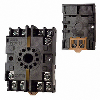
P2CF-11
Description
11 PIN Socket
Manufacturer
Omron
Type
Socketr
Specifications of P2CF-11
Number Of Positions
11
Mounting Type
DIN Rail
Termination Style
Screw Terminal
Accessory Type
Socket
Rohs Compliant
Yes
Associated Relay Series
H5CL
Number Of Poles
11
Mounting Style
DIN Rail
Lead Free Status / RoHS Status
Lead free / RoHS Compliant
For Use With/related Products
Multiple Series
For Use With
Z2998 - RELAY TIMER DGTL SPDT 100/240VACZ2366 - RELAY REPEAT CYCLE ANLG 30HRSZ997 - RELAY TIMER ANALOG 24VDC/ACZ2358 - RELAY REPEAT CYCLE ANLG 30HRSZ876 - RELAY TIMER DPDT ANALOG 120\240V
Lead Free Status / Rohs Status
Lead free / RoHS Compliant
Other names
P2CF11
Z884
Z884


Nomenclature
Operation
J DIP SWITCH SETTING
Time Ranges
Timer Control with Power Start
When using the H5CL with power start, short-circuit the start input and input 0-V terminals.
Indicator
Operation Key
Pin no.
1
ON
OFF
ON
OFF
ON
OFF
ON
OFF
1. Present Value
2. Preset Value
3. Reset Indicator (orange)
4. Key Protection Indicator (orange)
5. Time Unit Display (orange)
6. Control Output Indicator (orange)
7. Reset (RST) Key
8. Increment Keys (1 to 4)
9. Decrement Keys (1 to 4)
1, 2, 3
Red LEDs with a character height of 12 mm
Note: The decimal point will flash on the present value dur-
Green LEDs with a character height of 8 mm
The RST Key initializes the present value and control output.
Up Keys 1 to 4 increment the preset value.
Down Keys 1 to 4 decrement the preset value.
4
5
6
ing the timing operation in the following ranges:
0.1 to 999.9 min, 0 h 01 min to 99 h 59 min, and
0.1 to 999.9 h.
2
ON
OFF
OFF
ON
ON
OFF
OFF
ON
Item
Time ranges
Display modes
Min. pulse width of inputs
Operating modes
3
ON
OFF
OFF
OFF
OFF
ON
ON
ON
•
•
•
•
Time range
0.001 to 9.999 s
0.01 to 99.99 s
0.1 to 999.9 s
1 to 9999 s
0 min 01 s to 99 min 59 s
0.1 to 999.9 min
0 h 01 min to 99 h 59 min
0.1 to 999.9 h
Switches 1 to 6 are all set to OFF before shipping.
The same switch settings apply to AC and DC models.
Set the DIP switch before installation and operation of the unit.
DIP switch setting changes made while the power is ON cannot take effect.
OFF
See table below.
Up (Increment)
20 ms
A (signal ON-delay)
4
6
3
7
ON
Down (Decrement)
1 ms
F (cumulative operation)
4
Stick the enclosed label here.
1
2
5
8
9
Related parts for P2CF-11
Image
Part Number
Description
Manufacturer
Datasheet
Request
R

Part Number:
Description:
SOCKET 8-PIN FOR H3CR-H
Manufacturer:
Omron
Datasheet:

Part Number:
Description:
SOCKET 11-PIN FOR H3CR-H
Manufacturer:
Omron
Datasheet:

Part Number:
Description:
8 PIN Socket
Manufacturer:
Omron
Datasheet:


Part Number:
Description:
G6S-2GLow Signal Relay
Manufacturer:
Omron Corporation
Datasheet:
Part Number:
Description:
Compact, Low-cost, SSR Switching 5 to 20 A
Manufacturer:
Omron Corporation
Datasheet:
Part Number:
Description:
Manufacturer:
Omron Corporation
Datasheet:
Part Number:
Description:
Manufacturer:
Omron Corporation
Datasheet:
Part Number:
Description:
Manufacturer:
Omron Corporation
Datasheet:
Part Number:
Description:
Manufacturer:
Omron Corporation
Datasheet: