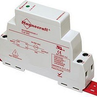
861SSR210-AC-2 Magnecraft / Schneider Electric, 861SSR210-AC-2 Datasheet - Page 27

861SSR210-AC-2
Manufacturer Part Number
861SSR210-AC-2
Description
Modular Style
Manufacturer
Magnecraft / Schneider Electric
Datasheet
1.70S2-01-A-05-N.pdf
(32 pages)
Specifications of 861SSR210-AC-2
Control Voltage Range
90 VAC to 280 VAC
Load Voltage Rating
24 VAC to 280 VAC
Load Current Rating
10 A
Contact Form
SPST - NO
Mounting Style
DIN Rail
Lead Free Status / RoHS Status
Lead free / RoHS Compliant
Lead Free Status / RoHS Status
Lead free / RoHS Compliant, Lead free / RoHS Compliant
Application Data
(continued)
Magnecraft
Heat Sinking
Thermal management is a fundamental consideration in the design and use of solid
state relays because of the dissipation (typically 1 watt per amp)� It is, therefore,
vital that an adequate heat sink is provided, or the life and switching reliability of the
SSR will be compromised� In order to properly size a heat sink one has to consider
the variables that comprise the thermal resistance Rth (in °C/W)�
Now that we have calculated the thermal resistance (Rth) we can look at the
thermal resistance vs� heat sink volume curve�
Using this curve with our example above, we can see that a heat sink volume of
approximately 1000 cm
generated by the device�
0.01
0.1
10
Therefore:
Tr:
Ta:
Th:
Vh:
Ih:
Ph:
Rth:
Tr
Ph
Rth
1
10
=
=
=
Temperature rise
Ambient temperature (example 22 °C)
Heat sink temperature (example 54 °C)
Voltage to heater (example 12 V)
Current to heater (example 3�5 A)
Power applied to heat sink
Thermal resistance (in °C/W)
Thermal Resistance vs Heat Sink Volume
Th – Ta
Vh 3 Ih
Tr ÷ Ph =
3
would be needed to successfully sink the amount of heat
Natural convection at 50 C rise above ambient
®
100
Solid State Relays
HEAT SINK VOLUME (cm
=
=
1,000
54 – 22
12 3 3�5 = 42 W
32 ÷ 42 = 0�76 °C/W
10,000
= 32 °C
3
)
100,000
27


