VX-012-1A3 Omron, VX-012-1A3 Datasheet - Page 2
VX-012-1A3
Manufacturer Part Number
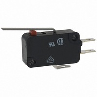
VX-012-1A3
Description
MICRO SWITCH HINGE LEVER SPDT 100mA 125V
Manufacturer
Omron
Series
VXr
Specifications of VX-012-1A3
Microswitch Type
Miniature
Actuator Style
Hinge Lever
Operating Force Max
30gf
Contact Voltage Ac Nom
125V
Contact Voltage Dc Nom
30V
Contact Current Max
100mA
Circuit
SPDT
Switch Function
On-Mom
Contact Rating @ Voltage
0.1A @ 125VAC
Actuator Type
Lever, Straight
Mounting Type
Chassis Mount
Termination Style
Solder, Quick Connect - .187" (4.7mm)
Operating Force
30gf
Contact Form
SPDT
Contact Rating
0.1 Amp
Actuator
Lever, Hinge
Lead Free Status / RoHS Status
Lead free / RoHS Compliant
Lead Free Status / RoHS Status
Lead free / RoHS Compliant, Lead free / RoHS Compliant
Other names
SW987
VX-012-1A3
VX0121A3
VX-012-1A3
VX0121A3


Specifications
■ Characteristics
Note: 1. Data shown are of initial value.
■ Ratings
Note: 1. Inductive load has a power factor of 0.4 min. (AC) and a time constant of 7 milliseconds max. (DC).
■ Approved Standards
UL Recognized (File No. E41515)
CSA Certified (File No. LR21642)
EN61058-1 - - VDE approval (File No. 124761)
Testing conditions: 5E4 (50,000 operations), T105 (0°C to 105°C)
136
Operating speed
Operating frequency
Contact resistance
Insulation resistance
Dielectric strength (see note 2)
Vibration resistance (see note 3)
Shock resistance (see note 3)
Degree of protection
Degree of protection against electric shock
Proof tracking index
Ambient operating temperature
Ambient operating humidity
Service life
Weight
Type
5 A
0.1 A
Rated Voltage
125 VAC
250 VAC
30 VDC
Rated Voltage
125 VAC
250 VAC
2. The dielectric strength shown is measured using a separator between the switch and metal mounting plate.
3. For the pin plunger models, the above values apply for use at the free position and total travel position. For lever models, they apply at
2. Lamp load has an inrush current of 10 times the steady-state current
3. The electrical rating applies under the following test conditions:
the total travel position. Contact separation time is within 1 ms.
Ambient Temperature = 20±2°C, Ambient Humidity = 65±5%, Operating frequency = 30 operations/minute
Snap Action Switch
Rated voltage
250 VAC
125 VAC
8 VDC
30 VDC
125 VDC
250 VDC
125 VAC
8 VDC
30 VDC
(reference values)
Item
VX-5
VX-5
5 A
5 A
- - -
5 A
5 A
Mechanical
Electrical
VX
NC
Resistive load
VX-01
VX-01
0.1 A
0.1 mm to 1 m/s (pin plunger models)
Mechanical: 600 operations per minute
Electrical: 30 operations per minute
30 mΩ max.
100 MΩ min. at 500 VDC
1,000 VAC, 50/60 Hz for 1 minute between terminals of same polarity
1,500 VAC, 50/60 Hz for 1 minute between current-carrying metal parts and ground and
between each terminal and non-current-carrying metal parts
Malfunction: 10 to 55 Hz, 1.5 mm double amplitude
IEC IP40
Class I
175
-25°C to 80°C (at 60% RH max.) with no icing
85% max (for 5°C to 35°C)
50,000,000 operations min. (60 ops/minute)
500,000 operations min. (30 ops/minute)
Approx. 6.2 g (pin plunger models)
0.1 A
0.1 A
Destruction: 400 m/s
Malfunction: 100 m/s
- - -
- - -
0.4
0.3
0.1
0.1
0.1
5
5
5
5
NO
VX-5
2
2
(approx. 40G) max.
(approx. 10G) max
■ Contact Specifications
Note: Minimum applicable loads are indicated by N standard refer-
Specification
Material
Gap (standard value)
Inrush current
Minimum applicable load
(see note)
NC
ence values. This value represents the failure rate at a 60%
(λ
The equation
rate of 1/2,000,000 operations can be expected at a reliability
level of 60%
60
Lamp load
) reliability level (JIS C5003).
Item
0.05
- - -
- - -
- - -
- - -
0.5
0.1
3
3
λ
NO
60
50 mΩ max.
10,000,000 operations min. (60 ops/minute)
1,000,000 operations min. (30 ops/minute)
=0.5 x 10
NC: 15A max.
NO:
160 mA at 5 VDC
Silver alloy
-6
/ operations indicates that a failure
Rivet
VX-5
- - -
NC
VX-01
Inductive load
0.5 mm
- - -
- - -
- - -
- - -
0.4
0.2
4
4
4
1 mA at 5 VDC
Gold alloy
Crossbar
VX-01
- - -
NO
Related parts for VX-012-1A3
Image
Part Number
Description
Manufacturer
Datasheet
Request
R

Part Number:
Description:
MINIATURE BASIC SWITCH
Manufacturer:
Omron
Datasheet:


Part Number:
Description:
G6S-2GLow Signal Relay
Manufacturer:
Omron Corporation
Datasheet:
Part Number:
Description:
Compact, Low-cost, SSR Switching 5 to 20 A
Manufacturer:
Omron Corporation
Datasheet:
Part Number:
Description:
Manufacturer:
Omron Corporation
Datasheet:
Part Number:
Description:
Manufacturer:
Omron Corporation
Datasheet:
Part Number:
Description:
Manufacturer:
Omron Corporation
Datasheet:
Part Number:
Description:
Manufacturer:
Omron Corporation
Datasheet:
Part Number:
Description:
Manufacturer:
Omron Corporation
Datasheet:
Part Number:
Description:
Manufacturer:
Omron Corporation
Datasheet: