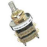
SERIES 53, 57 and 59
1.125" Diameter, 1/4 Amp
DIMENSIONS
STANDARD STYLE
MILITARY QUALIFIED
The Series 53, 57 and 59 rotary switches are all
military type switches. Grayhill manufactures
these switches in two styles: M and HS. Style M
is unsealed and is not qualified; Style HS is shaft
and panel sealed and is qualified. The non-
qualified Style M can be regarded as our
Standard Style for types of switches. Although
it is not qualified, Style M is constructed of the
same military grade materials and will provide
comparable performance in all areas. For
example, the Style ‘M’ switches, in addition to
the electrical ratings listed elsewhere in these
pages, will meet the following requirements of
MIL-S-3786:
Moisture Resistance: Medium and High Shock;
Vibration (10 to 500 cps); Thermal Shock (-65
°C to 125 °C); Salt Spray; Explosion; Terminal
Strength (pull, 2 lbs. minimum); and Stop
Strength (15 pound-inches minimum).
Military Style
Grayhill part number and date code marked on detent cover label. Customer part number marked on request. Military
part number marked when required.
Mounting Hardware: Two mounting nuts, .094" (2,39) thick by .562" (14,27) across flats, one internal tooth lockwasher
and one non-turn washer (see detail D for dimensions), are supplied with switch.
No. of
Decks
1
2
3
4
5
6
(5.56 ± 0,10)
.219 ± .004
1.125 ± .010 (28,58 ± 0,25)
Ser. 53—1.281 (32,54)
1.249 (31,72)
1.582 (40,18)
1.915 (48,64)
2.248 (57,10)
2.831 (71,91)
Dimension
Ser. 57 & 59—
.916 (23,27)
In inches (and millimeters)
A
C L
SEE
CIRCUIT
DIAGRAM
Dimension
.032 (0,81)
.032 (0,81)
.032 (0,81)
.032 (0,81)
.032 (0,81)
.281 (7,14)
B
C L
C
L
45°
OF POSITION
NO. 1
OF BUSHING
KEYWAY
C L
Approx.
Weight
Grams
100
50
60
70
80
90
.250 ± .020
(6,35 ± 0,51)
The line drawings shown above are applicable
to the Style M and Style HS. The only difference
between the two is the length of the tab of the
non-turn washer. The shorter tab for the HS is
explained in the following paragraph.
The Series 53, 57 and 59 Style HS rotary
switches are qualified to MIL-S3786/36. The
Style HS is shaft and panel sealed. The panel is
sealed by an O-ring at the base of the bushing.
The shaft is sealed by an O-ring inside the
bushing. These seals do not alter the dimensions
shown in the line drawings when the switch is
mounted.
A non-turn washer, supplied with the mounting
hardware, may be used with the Style HS
switches. It is suggested that the non-turn washer
be mounted in the following manner to preserve
the seal: from the front of the panel into a hole
that does not go through the panel.
FEATURES
• Smallest Diameter Rotary Switch
• Military Qualified MIL-S-3786/36
• Gold-plated Contact System
BUSHING KEYWAY
.066 ± .002 (1,68 ± 0,05) WIDE
BY .036 ± .003 (0,91 ± 0,08)
DEEP FROM A .375 (9,53) DIA.
No. of
Decks
with this Number of Positions and
Current Capacity
Compatible with Logic Circuitry
10
11
12
7
8
9
.250 + .001
–.002 DIA.
(6,35 + 0,03
–0,05)
3.164 (80,37)
3.497 (88,82)
3.830 (97,28)
4.163 (105,74)
4.496 (114,20)
4.829 (122,66)
.437
±.020
(11,10
±0,51)
Dimension
A
.437
±.020
(11,10
±0,51)
Dimension
.281 (7,14)
.281 (7,14)
.281 (7,14)
.281 (7,14)
.281 (7,14)
.281 (7,14)
B
DIM. A
INTEGRAL ASSEMBLY NUT. DO NOT REMOVE.
3/8-32 NEF-2A THREAD
MILITARY NUMBERS MARKED HERE
+ .046 (1,17)
– .020 (0,51)
Approx.
Weight
Grams
110
120
130
140
150
160
The qualification of the Series 53, 57 and 59
rotary switches does not extend to all possible
combinations listed in the Choices and
Limitations chart. The limitations on the
qualification are described in the chart shown
below.
Standard variations, such as shaft and/or
bushing length, etc., that do not affect switch
performance can also be marked as qualified
product. For complete details contact Grayhill.
Military qualified Series 53, 57 and 59 Style HS
rotary switches may be ordered by the ‘M’
number listed in MIL-S-3786/36 or by the Grayhill
part number. Military style switches will be
marked to the specification.
Qualified for the Following Characteristics
Series
1.000 (25.4) SER. 57 & 59
Style HS Switches are MIL-S-3786/36
53
57
59
1.156 (29.36) SER. 53
DIM. B REF. STUD
PROJECTION
Non-Turn Washer Detail D
STYLE M—.187 (4,75)
STYLE HS—.125 (3,18)
± .010 (0,25)
± .010 (0,25)
Max. No.
of Decks
5
5
5
Poles/Deck
.375 ± .005
(9,53 ± 0,13)
Max. No.
.125
± .003
(3,18
± 0,08)
8
4
5
Rear views
shown with circuit
diagrams
Total Poles/Switch
.032 ± .003
(0,81 ± 0,08)
Max. No.
24
20
20