56SDP36-01-1-AJS Grayhill Inc, 56SDP36-01-1-AJS Datasheet - Page 2
56SDP36-01-1-AJS
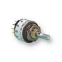
Manufacturer Part Number
56SDP36-01-1-AJS
Description
SWITCH, 1POLE, 10 POS
Manufacturer
Grayhill Inc
Datasheet
1.56D30-01-1-AJN.pdf
(4 pages)
Specifications of 56SDP36-01-1-AJS
No. Of Poles
1
No. Of Switch Positions
10
Contact Current Ac Max
200mA
Contact Current Dc Max
200mA
Contact Voltage Ac Max
115V
Contact Voltage Dc Max
30V
Svhc
No SVHC (15-Dec-2010)
Angle
36°
Behind
RoHS Compliant
Angle Of Throw
36°
Rohs Compliant
Yes


SPECIFICATIONS
Electrical Ratings
Chart shown for non-shorting (break before make)
contacts, resistive load.
One cycle is 360° rotation clockwise and 360°
return. The data for the curve was measured at
sea level, 25°C and 68% relative humidity with
the life limiting criteria which follows.
Contact Resistance: 100 milliohms maximum,
(15 milliohms initially).
Insulation Resistance: 10,000 Mohms
minimum between mutually insulated parts
(50,000 Mohms initially).
Voltage Breakdown: 600 Vac minimum
between mutually insulated parts at standard
atmospheric pressure.
Life Expectancy: As determined from the load-
life curve for the current to be switched. Contact
GRAYHILL for more information if any of the
following is true: the life limiting criteria are more
CIRCUIT DIAGRAMS AND REAR VIEWS: PC Mountable AND Solder Lug Terminals
POS. 1
POS. 1
300
200
100
36° TYP.
15°
30° TYP.
18°
0
0
COMMON LOCATION
FOR 1 POLE SWITCH
COMMON LOCATION
FOR 1 POLE SWITCH
115 Vac 0r 30 Vdc
CYCLES x 1000
10
Rear View
.366 ± .015
(9,30 ± 0,38)
DIA. CIRCLE
OF CENTERS
20
.340 ± .015
(8,64 ± 0,38) DIA.
CIRCLE OF CENTERS
COMMON LOCATION
FOR 2 POLE SWITCH
COMMON LOCATION
FOR 2 POLE SWITCH
.190 ± .015 (4,83 ± 0,38)
DIA. CIRCLE OF CENTERS
DIMENSION A
DIA. CIRCLE OF CENTERS
30
(PC MOUNT AND
SOLDER LUG)
Dimension
critical than those listed; longer operation is
required; a larger make and break current is
required; the operating environment includes
elevated temperatures or reduced pressures.
Contact Carry Rating: Switch will carry 6
amperes continuously with a maximum
contact temperature rise of 20°C.
Additional Characteristics
Contact Type and Forces: Shorting or non-
shorting wiping contacts with over 25 grams of
contact force.
Shaft Flat Orientation: Flat opposite contacting
position of pole number one (see circuit diagrams).
Terminals: Switches have the full circle of
terminals, regardless of number of active positions.
Stop Strength: 7.5 lb-in. minimum
Rotational Torque: 3.5 to 9 oz-in. (21-53 mN-
m), depending on the number of poles.
Bushing Mounting: Required for switches with
stops, and recommended for switches without
stops.
Meets MIL-S-3786 for:
High and medium shock; Vibration (10 to 2,000
Hz); Thermal shock (-65° to 85 ° C); Salt spray;
Explosion; Stop strength (7.5 in-lbs. minimum
(.85 N-m); Terminal strength; Sealed styles
withstand water pressure of 15 PSI minimum
(103 KPa) without leakage.
A
POS. 1
30° TYP.
15°
PC Mount
Terminals
.184 ± .015
(4,67 ± 0,38)
Solder Lug
Terminals
.126 ± .015
(3,20 ± 0,38)
Circuit as Viewed From Shaft End
.366 ± .015
(9,30 ± 0,38)
DIA. CIRCLE
OF CENTERS
.190 ± .015 (4,83 ± 0,38)
DIA. CIRCLE OF CENTERS
(PC MOUNT AND
SOLDER LUG)
6
5
7
6
8
5
4
7
TWO POLES
ONE POLE
4
9
C1
8
3
C2
10
3
Materials and Finishes
Housing: Zinc die cast, zinc-plated with chromate
treatment.
Mounting Nut: Brass, zinc-plated with chromate
treatment.
Lockwasher: Spring steel, zinc-plated with
chromate treatment.
Panel Seal: Silicone rubber
Shaft and Stop Arm: Zinc die cast, zinc-plated
with chromate treatment.
Retaining Ring: 302 Stainless steel, passivated
Shaft Seal: Silicone rubber
Stop Pins: 303 Stainless steel, passivated
Detent Rotor: Molded thermoplastic
Detent Spring: Tinned music wire
Detent Balls: Steel, nickel-plated
Contact Spring: Stainless steel, passivated
Rotor Contact: Brass, silver over nickel plate
Common Ring: Brass, gold over silver over
nickel plate
Terminals: Brass, gold over silver over nickel
plate
Switch Base: Molded thermoset plastic
Mounting Hardware: One mounting nut .089"
thick by .375" across flats and one internal tooth
lockwasher are supplied with the switch.
9
11
2
2
10
12
1
1
6
5
7
6
7
6
8
8
5
5
4
FOUR POLES
7
TWO POLES
ONE POLE
C2
9
4
9
4
C1
C3
8
3
C1
C2
10
10
3
3
C4
11
9
2
2
11
2
12
10
1
12
1
1
36° Angle
of Throw
30° Angle
of Throw
Related parts for 56SDP36-01-1-AJS
Image
Part Number
Description
Manufacturer
Datasheet
Request
R

Part Number:
Description:
SWITCH, ROTARY, DP5T, 200mA, 115V
Manufacturer:
Grayhill Inc
Datasheet:
Part Number:
Description:
SWITCH, ROTARY, SP10T, 200mA, 115V
Manufacturer:
Grayhill Inc

Part Number:
Description:
Rotary Switch, Shaft/panel Seal, Adjustable Stop, PC Mount, 36°
Manufacturer:
Grayhill Inc
Datasheet:
Part Number:
Description:
Rotary Switch, Shaft/panel Seal, Adjustable Stop, PC Mount, 36°
Manufacturer:
Grayhill Inc
Part Number:
Description:
Rotary Switch, Shaft/panel Seal, Adjustable Stop, PC Mount, 36°
Manufacturer:
Grayhill Inc
Datasheet:
Part Number:
Description:
Rotary Switch, Shaft/panel Seal, Adjustable Stop, PC Mount, 36°
Manufacturer:
Grayhill Inc
Part Number:
Description:
Encoder; 32pos; custom switching; sealed; continous rotation;
Manufacturer:
Grayhill Inc
Part Number:
Description:
50EPT90-01-1-04N-C SINGLE DECK ROTARY 0.5(12.7mm)DIA,200mA,Continuous
Manufacturer:
Grayhill Inc
Part Number:
Description:
Rotary Switch seal adj.stop 36� 1deck 1pol/deck 56BSD36-01PAJN -bulk
Manufacturer:
Grayhill Inc
Part Number:
Description:
Rotary Switch, Screwdriver slot shaft, shaft/panel seal, PC mount, 30°
Manufacturer:
Grayhill Inc
Part Number:
Description:
Encoder MODIFIED SPECIAL VERSION OF GRH'S 60A18-4-040C
Manufacturer:
Grayhill Inc
Part Number:
Description:
GRAYHILL,SERIES 71,ROTARY SWITCH,1/8 SHAFT,30DEGREE,DECK,1 POLE/DECK,12POSITION/POLE,NON-SHORTING,CONTINUOUS .
Manufacturer:
Grayhill Inc