71ADF30-01-2-AJN Grayhill Inc, 71ADF30-01-2-AJN Datasheet - Page 5
71ADF30-01-2-AJN
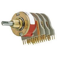
Manufacturer Part Number
71ADF30-01-2-AJN
Description
SWITCH, ROTARY, DP6T, 300mA, 115V
Manufacturer
Grayhill Inc
Type
Rotaryr
Datasheet
1.71SS1073-1.pdf
(14 pages)
Specifications of 71ADF30-01-2-AJN
No. Of Poles
2
No. Of Switch Positions
6
Angle Of Throw
30°
Contact Current Ac Max
300mA
Contact Voltage Ac Max
115V
Contact Voltage Dc Max
30V
Circuitry
DP6T
No. Of Decks
1
Actuator Type
Shaft
Current, Rating
300 mA
Dielectric Strength
500 VAC
Mounting Type
PCB
Number Of Poles
2
Special Features
Adjustable Stop
Termination
PC Pin
Voltage, Rating
115/30 VAC/VDC
Contact Current Max
250mA
Rohs Compliant
Yes
Lead Free Status / RoHS Status
Lead free / RoHS Compliant


SERIES 71: PC Board Pattern In inches (and millimeters)
SERIES 71: PC MOUNT ACCESSORY
Rotary
1
In inches (and millimeters)
All Styles Except 71BT
/
6
8
" and
(6,48 ± 0,05) DIA.
.255 ±.002
0.030 ±.001
(0,76 ± 0,03)
Grayhill, Inc. • 561 Hillgrove Avenue • LaGrange, Illinois
1
/
.207 ±.005
(5,26 ± 0,13)
4
For printed circuit styles. Mounting bushing provides additional
support for the front end of the switch. Order separately by
appropriate part number. Rotary switch discount applies.
Spacer decks can be supplied to facilitate PC board layouts of
three or more decks. A spacer deck does not have any
terminals and provides no switching function. Dimensionally, it
requires the same space as one normal switch deck. Spacer
deck can be placed at any location in the switch, per your
instructions. Switches which include spacer decks are procured
under a special part number.
" Diameter Shaft Styles
FOR USE WITH
PART 71C2054
STYLE AF
COMMON TERMINAL HOLE
B
30° Angle of Throw
LOCATION (SEE CHART)
Multi-Deck Rotary Switches
.075
(1,91)
TYP.
DIMENSIONS APPLY TO BOTH WASHERS.
SHAFT END
OF SWITCH
(3,30 ± 0,08)
0.368 ± .003
(9,35 ± 0,08)
.130 ±.003
.032 (0,81) THICK
.037 (0,94)
(7,62)
.300
TYP.
WASHER IS
C
L
A
.110 TYP.
.110 (2,79 )TYP.
FOR USE WITH
PART 71C2053
(2,79 )
STYLE BF
.500
±.002
(12,7
± 0,05)
60525-5997 • USA • Phone: 708-354-1040 • Fax: 708-354-2820 • www.grayhill.com
C
L
FOR DECK ONE
OF COMMON
.375 ± .002
(9,53 ± 0,05)
(17,45)
.687
DIA.
36° Angle of Throw
B
COMMON TERMINAL HOLE
Number of Poles
LOCATION (SEE CHART)
.075
(1,91)
TYP.
Per Deck
1
2
Bushing mount is recommended.
SHAFT END
OF SWITCH
Shown for a two deck switch.
.037 (0,94)
(7,62)
Metric Mount Styles
In millimeters
Ø 17.45
.300
TYP.
THICKNESS
0.81 ±0.05
±0.08
Common Terminal
A
Hole Location
A and B
FOR USE WITH
PART 71C2111
A
STYLE EF
12.7
±0.05
.110 TYP.
.110 (2,79 )TYP.
(2,79 )
0.76 ±0.03
±0.08
9.35
C
L
Related parts for 71ADF30-01-2-AJN
Image
Part Number
Description
Manufacturer
Datasheet
Request
R

Part Number:
Description:
SWITCH, ROTARY, SP12T, 300mA, 115V
Manufacturer:
Grayhill Inc
Datasheet:

Part Number:
Description:
Rotary Switch, 1/8" Shaft, Adjustable Stop, PC Mount, 30°
Manufacturer:
Grayhill Inc
Datasheet:

Part Number:
Description:
Rotary Switch, 1/8" Shaft, Adjustable Stop, PC Mount, 30°
Manufacturer:
Grayhill Inc
Datasheet:

Part Number:
Description:
Rotary Switch, 1/8" Shaft, Adjustable Stop, PC Mount, 30°
Manufacturer:
Grayhill Inc
Datasheet:

Part Number:
Description:
Rotary Switch, 1/8" Shaft, Adjustable Stop, PC Mount, 30°
Manufacturer:
Grayhill Inc
Datasheet:

Part Number:
Description:
Rotary Switch, 1/8" Shaft, Adjustable Stop, PC Mount, 30°
Manufacturer:
Grayhill Inc
Datasheet:
Part Number:
Description:
Rotary Switch, 1/8" Shaft, Adjustable Stop, PC Mount, 30°
Manufacturer:
Grayhill Inc
Datasheet:

Part Number:
Description:
Rotary Switch, 1/8" Shaft, Adjustable Stop, PC Mount, 30°
Manufacturer:
Grayhill Inc
Datasheet:
Part Number:
Description:
Rotary Switch, 1/8" Shaft, Adjustable Stop, PC Mount, 30°
Manufacturer:
Grayhill Inc
Datasheet:
Part Number:
Description:
Rotary Switch, 1/8" Shaft, Adjustable Stop, PC Mount, 30°
Manufacturer:
Grayhill Inc
Part Number:
Description:
Rotary Switch, 1/8" Shaft, Adjustable Stop, PC Mount, 30°
Manufacturer:
Grayhill Inc
Part Number:
Description:
Rotary Switch, 1/8" Shaft, Adjustable Stop, PC Mount, 30°
Manufacturer:
Grayhill Inc
Part Number:
Description:
Rotary Switch, 1/8" Shaft, Adjustable Stop, PC Mount, 30°
Manufacturer:
Grayhill Inc
Part Number:
Description:
Rotary Switch, 1/8" Shaft, Adjustable Stop, PC Mount, 30°
Manufacturer:
Grayhill Inc
Part Number:
Description:
Rotary Switch, 1/8" Shaft, Adjustable Stop, PC Mount, 30°
Manufacturer:
Grayhill Inc