51-295.022D EAO, 51-295.022D Datasheet - Page 39
51-295.022D
Manufacturer Part Number
51-295.022D
Description
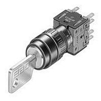
SWITCH, KEY LOCK, 1NO/1NC, 5A, 42V
Manufacturer
EAO
Datasheet
1.52-928.0.pdf
(64 pages)
Specifications of 51-295.022D
Contact Configuration
SPST
Switch Operation
ON-OFF
Angle Of Throw
90°
Actuator Style
Flat
No. Of Switch Positions
2
Contact Voltage Ac Nom
42V
Contact Voltage Dc Nom
42V
Lead Free Status / RoHS Status
Lead free / RoHS Compliant


Application guidelines
When switching inductive loads such as relays, DC motors, and DC solenoids, it is always important
to absorb surges (e.g. with a diode) to protect the contacts. When these inductive loads are switched
off, a counter emf can severely damage switch contacts and greatly shorten lifetime.
Fig. 1 shows an inductive load with a free-wheeling diode connected in parallel. This free-wheeling
diode provides a path for the inductor current to flow when the current is interrupted by the switch.
Without this free-wheeling diode, the voltage across the coil will be limited only by dielectric break-
down voltages of the circuit or parasitic elements of the coil. This voltage can be kilovolts in amplitude
even when nominal circuit voltages are low (e.g. 12 VDC) see Fig. 2.
The free-wheeling diode should be chosen so that the reverse breakdown voltage is greater than the
voltage driving the inductive load. The DC blocking voltage (VR) of the free-wheeling diode can be
found in the datasheet of a diode. The forward current should be equal or greater than the maximum
current flowing through the load.
To get an efficient protection, the free-wheeling diode must be connected as close as possible
to the inductive load!
0
VDC
Suppressor circuits
+
_
Switching with inductive load
Free-wheeling
Fig. 1
Switch
diode
Inductive
load
over load without free-wheeling diode
Sveral hundred
thousend volts
to several
Counter emf
0
Fig. 2
ON
OFF
e = L
__
dt
di
01.2010
37
51
Related parts for 51-295.022D
Image
Part Number
Description
Manufacturer
Datasheet
Request
R

Part Number:
Description:
51 470RA
Manufacturer:
Tyco Electronics
Datasheet:


Part Number:
Description:
Metal Film Resistors - Through Hole 1/2 WATT 51 OHM 5%
Manufacturer:
IRC

Part Number:
Description:
Metal Film Resistors - Through Hole 2watts 51ohms 2%
Manufacturer:
Vishay
Part Number:
Description:
51 22KB
Manufacturer:
Tyco Electronics
Datasheet:

Part Number:
Description:
Rotary Switch, Adjustable Stop, 30°
Manufacturer:
Grayhill Inc
Datasheet:

Part Number:
Description:
Rotary Switch, Adjustable Stop, 30°
Manufacturer:
Grayhill Inc
Datasheet:
Part Number:
Description:
Rotary Switch, Adjustable Stop, PC Mount, 30°
Manufacturer:
Grayhill Inc
Datasheet:

Part Number:
Description:
Switch, Keylock, 2 Pole, Two Position, Anti-Static
Manufacturer:
EAO Switch
Datasheet:
Part Number:
Description:
Keylock rotary switch, 2 position
Manufacturer:
EAO Switch
Datasheet:
Part Number:
Description:
Rotary Switch, Standard, 1/8" Shaft, 30°
Manufacturer:
Grayhill Inc
Datasheet:
Part Number:
Description:
Rotary Switch, PC Mount, 22.5°
Manufacturer:
Grayhill Inc
Datasheet:
Part Number:
Description:
54 1MA 6X30PL B8 HP
Manufacturer:
Tyco Electronics
Datasheet:

Part Number:
Description:
SWITCH, KEY LOCK, 1NO/1NC, 5A, 250V
Manufacturer:
EAO
Datasheet:
Part Number:
Description:
SWITCH, KEY LOCK, 1NO/1NC, 5A, 250V
Manufacturer:
EAO
Datasheet: