14-236.025K EAO, 14-236.025K Datasheet
14-236.025K
Specifications of 14-236.025K


Related parts for 14-236.025K


14-236.025K Summary of contents
Page 1
... EAO – Your Expert Partner for Human Machine Interfaces EAO Product Information Series 14 ...
Page 2
...
Page 3
... Switches and Indicators 14 ...
Page 4
... Contents Description ...................................................................................................... 3 Product Assembly .......................................................................................... 4 Devices raised mounting ............................................................................... 6 Devices flush mounting ............................................................................... 13 Accessories................................................................................................... 17 Technical Data............................................................................................... 27 Typical Applications ..................................................................................... 30 Application guidelines.................................................................................. 31 Marking .......................................................................................................... 32 Drawings........................................................................................................ 36 Index............................................................................................................... 56 2 07.2009 14 ...
Page 5
... Description Product Information General notes The Series 14 illuminated pushbuttons combine the robust actuators of the Series 04 with choice of either snap-action switching elements with gold plated silver contacts for one changeover only. These pushbuttons have proof front (temporary emerson) and can be immersed to a depth of one metre. ...
Page 6
... Illuminated pushbutton, flush mounting 07.2009 1 Front ring 2 Lens 3 Marking plate 4 LED 5 Actuator housing with switching element 6 Front plate 7 Fixing nut 1 Front bezel set, flush mounting 2 Lens 3 Marking plate 4 LED 5 Actuator housing with switching element 6 Front panel 7 Pressure ring 8 Fixing nut 14 ...
Page 7
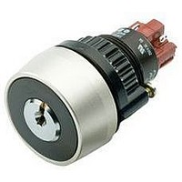
... Product Assembly Keylock switch, raised mounting Selector switch, flush mounting Front ring 2 Actuator housing with switching element 3 Front plate 4 Fixing nut 1 Front ring 2 Actuator housing with switching element 3 Front plate 4 Anti-twist ring 5 Pressure ring 6 Fixing nut 14 5 07.2009 ...
Page 8
... Continuation see next page Indicator actuator front illumination Terminals Soldering terminal Soldering terminal (also pluggable 2.8 x 0.5 mm Universal terminal Component layout from page 36, Mounting dimensions from page 37, Technical drawing from page 38, Circuit drawing from page 48 6 07.2009 Ø Typ-Nr 14-741.006 0.011 14-742.006 0.011 ...
Page 9
... Further information in the Technical Data and Typical Applications Terminals Soldering terminal (also pluggable 2.8 x 0.5 mm) Mounting dimensions from page 37, Technical drawing from page 38, Circuit drawing from page 48 Front cap IP 65 Brass nickel-plated Plastic black 14 Ø Typ-Nr. S1 14-810.902 0.016 S1 14-810.002 0.016 7 07.2009 ...
Page 10
... 20 42 0.015 14-475.036 0.015 14-435.036 0.015 14-472.036 0.015 14-432.036 0.015 14-471.036 0.015 14-431.036 0.015 14-747.0292 0.014 14-743.0292 0.014 14-748.0292 0.014 14-744.0292 0.014 14-271.0252 0.013 14-271.022 0.013 14-131.0252 0.013 14-131.022 0.013 14-749.0292 0.016 14-745.0292 0.016 14-750.0292 0.016 14-746.0292 0.016 14-272.0252 0.015 14-132.0252 ...
Page 11
... Terminals Universal terminal Soldering terminal Soldering terminal (also pluggable 2.8 x 0.5 mm) Component layout from page 36, Mounting dimensions from page 37, Technical drawing from page 38, Circuit drawing from page 48 Ø Contacts Typ-Nr 14-476.036 M UT 14-436.036 14-473.036 M UT 14-433.036 14-475.036 M UT 14-435.036 14-472.036 M UT 14-432.036 14-471 ...
Page 12
... 18 42 0.015 14-475.036 0.015 14-435.036 0.015 14-472.036 0.015 14-432.036 0.015 14-471.036 0.015 14-431.036 0.015 14-747.0292 0.014 14-743.0292 0.014 14-748.0292 0.014 14-744.0292 0.014 14-271.0252 0.013 14-271.022 0.013 14-131.0252 0.013 14-131.022 0.013 14-749.0292 0.016 14-745.0292 0.016 14-750.0292 0.016 14-746.0292 0.016 14-272.0252 0.015 14-132.0252 ...
Page 13
... Component layout from page 36, Mounting dimensions from page 37, Technical drawing from page 38, Circuit drawing from page 48 Ø Contacts Typ-Nr 14-415.036K C 14-418.036K 14-412.036K 14-414.036K C 14-417.036K 14-411.036K 14-235.025K2 C 14-335.025K2 14-135.025K2 S1 A 14-235.022K C 14-335.022K 14-135.022K 14-236.025K2 C 14-336.025K2 14-136.025K2 14-237.025K2 C 14-337.025K2 14-137.025K2 14-238.025K2 C 14-338.025K2 14-138.025K2 14-438.036K 14-437.036K 14-141.025K2 S1 A 14-141.022K ...
Page 14
... S 14-553.02502 0.028 14-559.02502 0.030 S 14-554.02502 0.030 14-522.0360 0.025 UT 14-517.0360 0.025 14-521.0360 0.025 UT 14-516.0360 0.025 14-520.0360 0.025 UT 14-515.0360 0.025 14-506.02502 0.024 S1 14-506.0220 0.024 S 14-501.02502 0.024 S1 14-501.0220 0.024 14-507.02502 0.026 S 14-502.02502 0.026 14-508.02502 0.028 S 14-503.02502 0.028 14-509.02502 0.030 S 14-504.02502 ...
Page 15
... Terminals Soldering terminal (also pluggable 2.8 x 0.5 mm) Mounting dimensions from page 37, Technical drawing from page 38, Circuit drawing from page Front cap IP 40 Aluminium black Aluminium natural 14 Ø Typ-Nr. 14-040.005 0.050 S1 14-040.002 0.050 UT 14-041.006 0.050 Ø Typ-Nr. S1 14-810.910 0.016 S1 14-810.918 0.016 13 07.2009 ...
Page 16
... 25 42 0.015 14-475.036 0.015 14-435.036 0.015 14-472.036 0.015 14-432.036 0.015 14-471.036 0.015 14-431.036 0.015 14-747.0292 0.014 14-743.0292 0.014 14-748.0292 0.014 14-744.0292 0.014 14-271.0252 0.013 14-271.022 0.013 14-131.0252 0.013 14-131.022 0.013 14-749.0292 0.016 14-745.0292 0.016 14-750.0292 0.016 14-746.0292 0.016 14-272.0252 0.015 14-132.0252 ...
Page 17
... 26 54 0.030 14-414.036K 0.030 14-417.036K 0.030 14-411.036K 0.030 14-235.025K2 0.029 14-335.025K2 0.029 14-135.025K2 0.029 14-235.022K 0.029 14-335.022K 0.029 14-135.022K 0.029 14-236.025K2 0.031 14-336.025K2 0.031 14-136.025K2 0.031 14-237.025K2 0.033 14-337.025K2 0.033 14-137.025K2 0.033 14-238.025K2 0.035 14-338.025K2 0.035 14-138.025K2 0.035 14-438.036K 0.030 14-437.036K ...
Page 18
... Contacts Normally closed Normally open Switching action Maintained action Momentary action Terminals Universal terminal Soldering terminal Soldering terminal (also pluggable 2.8 x 0.5 mm) Component layout from page 36, Mounting dimensions from page 37, Technical drawing from page 38, Circuit drawing from page 48 16 07.2009 Lever Contacts 14-522.0360 14-521.0360 14-520.0360 M ...
Page 19
... Lens Aluminium black flush Aluminium blue flush Aluminium gold flush Aluminium natural flush Aluminium olive-green flush Aluminium red flush Stainless steel natural flush 14 Ø Typ-Nr. 704.602.0 0.001 704.602.6 0.001 704.602.7 0.001 704.602.5 ...
Page 20
... Typ-Nr. 704.604.0 0.001 704.604.5 0.001 704.604.2 0.001 704.604.4 0.001 Ø Typ-Nr. 704.614.6 0.007 704.614.7 0.007 704.614.5 0.007 704.614.2 0.007 704.614.4 0.007 e Typ-Nr. 704.609.7 0.001 704.609.9 0.001 704.609.0 0.001 e Typ-Nr. 704.609.9 0.001 ...
Page 21
... Plastic colourless transparent ribbed Plastic white translucent Front Bezel Aluminium black Aluminium natural 14 e Typ-Nr. 704.610.7 0.001 704.610.9 0.001 e Typ-Nr. 704.608.7 0.002 704.608.9 0.002 Ø Typ-Nr. 704.600.0 0.003 704.600.6 0.003 704.600.1 0.005 704.600.1A 0.005 704.600.9 0.006 Ø Typ-Nr. 14-958 0.042 14-958 0.042 19 07.2009 ...
Page 22
... Technical drawing from page 38 Legend plate insert for Legend frame 704.968.2 and 704.968.3 Continuation see next page Legend plate insert 14.5 x 23.5 mm, adhesive, Aluminium black 14.5 x 23.5 mm, adhesive, Aluminium natural Protective cover, raised mounting Mounting hole size 22.5 mm dia. Continuation see next page ...
Page 23
... Silicone colourless transparent 704.953.0 Ø Front protective ring Typ-Nr. Aluminium natural 704.600.5/A Aluminium natural 704.600.3 Chromed brass 704.600.2 Ø Front bezel Typ-Nr. Aluminium black 704.955.4 Aluminium natural 704.955.3 Stainless steel natural 704.955.9E 0.033 14 e 0.019 0.019 0.019 e 0.002 e 0.005 0.005 0.005 e 0.015 0.015 21 07.2009 ...
Page 24
... Flat receptacle Continuation see next page Flat receptacle 2.0 x 0.5 mm for Universal terminal 2.8 x 0.5 mm for Plug-in terminal 22 07.2009 Blind plug Typ-Nr. Plastic black IP 65 704.960.4 Plastic black IP 65 704.964.8 Typ-Nr. 14-987.1001 0.006 Typ-Nr. 31-940 31-942 31-941 Typ-Nr. 31-945 31-946 0.004 2 0.007 ...
Page 25
... Operating voltage/-current Typ-Nr. 12 VAC/DC, 100 mA 10-1109.1329 12 VAC/DC 10-1109.1279 24 VAC/DC 10-1112.1199 24 VAC/DC 10-1112.1279 28 VAC/DC 10-1113.1249 30 VAC/DC 10-1114.1249 36 VAC/DC 10-1116.1229 48 VAC/DC 10-1119.1199 6 VAC/DC, 200 mA 10-1106.1369 14 e Typ-Nr. 01-928 0.001 31-928 0.001 31-929 0.001 e Typ-Nr. 01-929 0.010 e 0.001 0.001 0.001 0.001 0.001 0.001 ...
Page 26
... VDC 10-2106.3145 12 VAC/DC, 7/14 mA 10-2109.1062 24 VAC/DC, 7/14 mA 10-2112.1062 28 VAC/DC, 7/14 mA 10-2113.1062 48 VAC/DC, 4/8 mA 10-2119.1042 6 VDC 10-2106.3142 12 VAC/DC, 7/14 mA 10-2109.1069 24 VAC/DC, 7/14 mA 10-2112.1069 28 VAC/DC, 7/14 mA 10-2113.1069 48 VAC/DC, 4/8 mA 10-2119.1049 6 VDC 10-2106.3149 12 VAC/DC, 7/14 mA 10-2109.1064 24 VAC/DC, 7/14 mA 10-2112.1064 28 VAC/DC, 7/14 mA 10-2113.1064 48 VAC/DC, 4/8 mA 10-2119 ...
Page 27
... Lens plug for round lens, flush mounting for mounting and dismantling of Lens round, flush mounting Lamp remover Continuation see next page Lamp remover CAUTION A switching process might be released when replacing the Lamp/LED ! 14 e Typ-Nr. 14-910 3 0.001 e Typ-Nr. 704.954.0 0.002 e Typ-Nr. 704.960.0 ...
Page 28
... L 180 mm mm with mounting hole 4 x 22.5 mm dia., with anti-twist device L 180 mm, W 182 mm, H 110 mm 704.945.4 14 0.572 with mounting hole 6 x 22.5 mm dia., with anti-twist device L 180 mm, W 182 mm, H 110 mm 704.945.5 15 0.568 Openings for cable gland M16 or M20 ...
Page 29
... Protection degree as per EN IEC 60529 front side IP 67 Shock resistance (semi-sinusoidal) max. 150 m/s², pulse width 11 ms, 3-axis, as per EN IEC 60068-2- 27 Vibration resistance (sinusoidal) max. 100 m/s² ... 500 Hz, as per EN IEC 60068-2 220 VDC 0 07.2009 ...
Page 30
... EN IEC 60068-2- 27 > Buzzer Buzzer system System Piezo disc Material Alarm buzzer case Polyamide Front cap Plastic Polyamide Metal Nickel-plated brass (sea-water proof) Mechanical characteristics Terminals Plug-in terminal 2.8 x 0.5 mm Electrical characteristics Frequency (tone) approx. 2.8 kHz continuous tone only 14 ...
Page 31
... Operation Voltage/Current 0 24 VDC ±10 % Operation Voltage ≤25 mA Operation Current Environmental conditions Storage temperature -40 °C ... +85 °C Operating temperature -25 °C ... +55 °C Protection degree as per EN IEC 60529, frontside IP 40, devices flush mounting IP 65, devices raised mounting Approvals Declaration of conformity 07.2009 ...
Page 32
... Typical Applications Diode element When indicators and illuminated pushbuttons equipped with diodes, the user is able to perform a lamp check or wire an alarm circuit simply with a considerable saving of space 07.2009 14 ...
Page 33
... To get an efficient protection, the free-wheeling diode must be connected as close as possible to the inductive load! 0 Switching with inductive load Fig. 1 Switch + Free-wheeling Inductive VDC _ diode load Counter emf over load without free-wheeling diode Fig OFF 0 Sveral hundred to several thousend volts 07.2009 ...
Page 34
... Marking General notes 0 1. Engraving In addition to the most commonly used world languages, in DIN 1451-3 close spacing, other typefaces are available as Scandinavian, Slavic, Greek, Russian and Polish. The lenses are filled with black or white colour. Standard height of letters is 3 mm. If the height is not specified, we will supply 3 mm engraved letters ...
Page 35
... B1 30 The gap between 2 words results in each case a letter less. > Standard texts for marking plates and marking caps for Indicator and Illuminated Pushbutton Height of letters Height of letters Number of lines Number of (target value) Image letters per line 07.2009 ...
Page 36
... Marking > Symbols for marking plates and marking caps for Indicator and Illuminated Pushbutton 0 Continuation see next page > 34 07.2009 14 ...
Page 37
... Marking Continued from previous page 07.2009 ...
Page 38
... Mushroom-head actuator pushbutton page 9 | Illuminated mushroom-head actuator pushbutton page 10 | Keylock switch 2 positions page 11 | Selector switch 2 positions page 12 | Indicator actuator, flush mounting page 13 | Illuminated pushbutton actuator, flush mounting page 14 | Keylock switch actuator 2 positions, flush mounting page 15 | Selector switch actuator 2 positions, flush mounting page 16 ...
Page 39
... Mounting dimensions 1 Indicator actuator, flush mounting page 13 | Buzzer, flush mounting page 13 | Illuminated pushbutton actuator, flush mounting page 14 | Keylock switch actuator 2 positions, flush mounting page 15 | Selector switch actuator 2 positions, flush mounting page 16 | Front bezel set, flush mounting page 20 35 min. ...
Page 40
... Hole spacing 31 mm min. by using blind plug 704.960.4 Technical drawing 1 Buzzer page 7 35.5 13.5 26.5 2 ... 6 38 07.2009 for devices with anti-twist device (rotary) (recommended for keylock switch) 21.3 30 min. 14 for devices selector switch long lever 42 min. ...
Page 41
... Blind plug page 22 3 Blind plug page 22 4.8 20 2.5... Protective cover, raised mounting page 20 Front panel thickness reduces by 3 max. 4 Protective cover, flush mounting page 21 Front panel thickness reduces by 2 max. 3 Protective cover, raised mounting page 20 Front panel thickness reduces by 3 max. 4 07.2009 ...
Page 42
... Drawings 7 Protective cover, flush mounting page 21 Front panel thickness reduces by 2 max. 3 Protective cover, flush mounting page 21 Front panel thickness reduces by 2 max. 3 Legend frame page 20 23 Legend frame page 20 23 07.2009 14 ...
Page 43
... Drawings 11 Enclosure page Enclosure page 26 130 50 90 115 14 41 07.2009 ...
Page 44
... Drawings 13 Enclosure page 26 180 100 120 165 14 Enclosure page 26 182 50 120 167 42 07.2009 14 ...
Page 45
... Drawings 15 Enclosure page 26 182 50 50 120 167 16 Buzzer, flush mounting page 13 46.5 2 37.5 2 ... 07.2009 ...
Page 46
... L1 13 Mushroom-head actuator pushbutton page 9 | Illuminated mushroom-head actuator pushbutton page 10 40 13.5 1.5 ... Indicator actuator front illumination page 6 29 1.5 ... 07.2009 1D, 2D 1NC+1NO 3 2NC+2NO 3NC+3NO 4NC+4NO 1NC+1NO 2NC+2NO+D 1NC, 1NO, 1NC+1NO, 2NC, 2NO 37.5 45.5 44 44 37 44.5 - ...
Page 47
... Selector switch 2 positions page 12 29 13.5 1.5 ... 1NC+1NO 3 2NC+2NO 3NC+3NO 4NC+4NO 1NC+1NO 2NC+2NO+D 1NC, 1NO, 1NC+1NO, 2NC, 2NO 3 1NC+1NO 2NC+2NO 3NC+3NO 4NC+4NO U 1NC, 1NO, 1NC+1NO, 2NC, 2NO L 3 1NC+1NO 35.5 2NC+2NO 43 3NC+3NO 50.5 4NC+4NO 58 U 1NC, 1NO, 1NC+1NO, 2NC, 2NO 37 35.5 45.5 ...
Page 48
... Drawings 23 Selector switch 2 positions page 12 29 13.5 1.5 ... Indicator actuator, flush mounting page 13 35 1.5 ... Illuminated pushbutton actuator, flush mounting page 14 35 1.5 ... 07.2009 3 1NC+1NO 2NC+2NO 3NC+3NO 4NC+4NO U 1NC, 1NO, 1NC+1NO, 2NC, 2NO 48.5 56.5 55.5 1NC+1NO 3 2NC+2NO 3NC+3NO 4NC+4NO 1NC+1NO+D ...
Page 49
... L1 15 Front bezel set for Mushroom-head pushbutton page 1.5 ... 6 13 1NC+1NO 2NC+2NO 3NC+3NO 4NC+4NO L1 U 1NC+1NO, 2NO 3 1NC+1NO 2NC+2NO 3NC+3NO 4NC+4NO U 1NC+1NO, 2NC, 2NO 1NC+1NO 48 2NC+2NO 3NC+3NO 63 4NC+4NO 1NC+1NO 63.5 2NC+2NO 1NC, 1NO, 1NC+1NO, 2NC, 2NO 55 07.2009 14 ...
Page 50
... Indicator actuator full face illumination page 6 | Indicator actuator front illumination page 6 | Indicator actuator, flush mounting page 13 a-(x1) b+(x2) 3 Indicator actuator full face illumination page 6 | Indicator actuator front illumination page 6 | Indicator actuator, flush mounting page 13 4 Illuminated actuator pushbutton page 8 | Mushroom-head actuator pushbutton page 9 | Illuminated mushroom-head actuator pushbutton page 10 | Illuminated pushbutton actuator, flush mounting page ...
Page 51
... Illuminated pushbutton actuator, flush mounting page Illuminated actuator pushbutton page 8 | Mushroom-head actuator pushbutton page 9 | Illuminated mushroom-head actuator pushbutton page 10 | Illuminated pushbutton actuator, flush mounting page Illuminated actuator pushbutton page 8 | Mushroom-head actuator pushbutton page 9 | Illuminated mushroom-head actuator pushbutton page 10 | Illuminated pushbutton actuator, flush mounting page 07.2009 ...
Page 52
... Drawings 15 Illuminated actuator pushbutton page 8 | Mushroom-head actuator pushbutton page 9 | Illuminated mushroom-head actuator pushbutton page 10 | Illuminated pushbutton actuator, flush mounting page Illuminated actuator pushbutton page 8 | Mushroom-head actuator pushbutton page 9 | Illuminated mushroom-head actuator pushbutton page 10 | Illuminated pushbutton actuator, flush mounting page Selector switch 2 positions page 12 | Selector switch actuator 2 positions, flush mounting page 16 ...
Page 53
... Selector switch 2 positions page 12 | Selector switch actuator 2 positions, flush mounting page Selector switch 2 positions page 12 | Selector switch actuator 2 positions, flush mounting page Selector switch 2 positions page 12 | Selector switch actuator 2 positions, flush mounting page Selector switch 2 positions page 12 | Selector switch actuator 2 positions, flush mounting page III III 07.2009 ...
Page 54
... Drawings 30 Selector switch 2 positions page 12 | Selector switch actuator 2 positions, flush mounting page Illuminated actuator pushbutton page 8 | Mushroom-head actuator pushbutton page 9 | Illuminated mushroom-head actuator pushbutton page 10 | Illuminated pushbutton actuator, flush mounting page III Illuminated actuator pushbutton page 8 | Mushroom-head actuator pushbutton page 9 | Illuminated mushroom-head actuator ...
Page 55
... Illuminated actuator pushbutton page 8 | Mushroom-head actuator pushbutton page 9 | Illuminated mushroom-head actuator pushbutton page 10 | Illuminated pushbutton actuator, flush mounting page Illuminated actuator pushbutton page 8 | Mushroom-head actuator pushbutton page 9 | Illuminated mushroom-head actuator pushbutton page 10 | Illuminated pushbutton actuator, flush mounting page Illuminated actuator pushbutton page 8 | Mushroom-head actuator pushbutton page 9 | Illuminated mushroom-head actuator ...
Page 56
... Keylock switch 2 positions page 11 | Keylock switch actuator 2 positions, flush mounting page Keylock switch 2 positions page 11 | Keylock switch actuator 2 positions, flush mounting page Keylock switch 2 positions page 11 | Keylock switch actuator 2 positions, flush mounting page Keylock switch 2 positions page 11 | Keylock switch actuator 2 positions, flush mounting page 07.2009 1 3 III III ...
Page 57
... Keylock switch 2 positions page 11 | Keylock switch actuator 2 positions, flush mounting page Keylock switch 2 positions page 11 | Keylock switch actuator 2 positions, flush mounting page Indicator actuator full face illumination page 6 a-(x1) 3(+) b+(x2) 4(-) 57 Indicator actuator full face illumination page 6 a-(x1) 3(+) 1(-) b+(x2) 4(-) 2(+) 1 3 III III 07.2009 ...
Page 58
... 14-136.025K2 .............................15 14-137.025K2 .............................11 14-137.025K2 .............................15 14-138.025K2 .............................11 14-138.025K2 .............................15 14-141.022K ...............................11 14-141.022K ...............................15 14-141.025K2 .............................11 14-141.025K2 .............................15 14-142.025K2 .............................11 14-142.025K2 .............................15 14-143.025K2 .............................11 14-143.025K2 .............................15 14-144.025K2 .............................11 14-144.025K2 .............................15 14-235.022K ...............................11 14-235.022K ...............................15 14-235.025K2 .............................11 14-235.025K2 .............................15 14-236.025K2 .............................11 14-236.025K2 .............................15 14-237.025K2 .............................11 14-237.025K2 .............................15 14-238.025K2 .............................11 14-238.025K2 .............................15 14-271.022 .................................10 14-271.022 .................................14 14-271.022 ...................................8 14-271.022 ...................................9 14-271.0252 ...............................10 14-271.0252 ...............................14 14-271.0252 .................................8 14-271.0252 .................................9 14-272.0252 ...............................10 14-272.0252 ...............................14 14-272.0252 .................................8 14-272.0252 .................................9 14-273.0252 ...............................10 14-273.0252 ...............................14 14-273.0252 .................................8 14-273.0252 .................................9 14-274 ...
Page 59
... Typ-Nr. Page 14-748.0292 ............................... 14 14-748.0292 ................................. 8 14-749.0292 ............................... 10 14-749.0292 ............................... 14 14-749.0292 ................................. 8 14-750.0292 ............................... 10 14-750.0292 ............................... 14 14-750.0292 ................................. 8 14-810.002 ................................... 7 14-810.902 ................................... 7 14-810.910 ................................. 13 14-810.918 ................................. 13 14-910 ........................................ 25 14-958 ...
Page 60
... Switzerland Phone +41 62 388 95 00 Fax +41 62 388 95 55 E-mail sales.ech@eao.com United Kingdom Phone +44 1444 236 000 Fax +44 1444 236 641 E-mail sales.euk@eao.com USA Phone +1 203 877 4577 Fax +1 203 877 3694 E-mail sales.eus@eao.com Other Countries Phone +41 62 286 92 10 ...