A165E-M-02 Omron, A165E-M-02 Datasheet - Page 9
A165E-M-02
Manufacturer Part Number
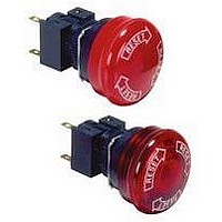
A165E-M-02
Description
SWITCH, EMERGENCY STOP, DPST-NC, 250VAC
Manufacturer
Omron
Series
A165Er
Datasheets
1.M2DA-7001.pdf
(265 pages)
2.A165E-S-02.pdf
(10 pages)
3.A165E-02.pdf
(17 pages)
4.A165E-M-02.pdf
(9 pages)
Specifications of A165E-M-02
Contact Configuration
DPST-NC
Switch Operation
Pushlock Turn Reset
Contact Voltage Ac Nom
250V
Contact Voltage Dc Nom
30V
Contact Current Max
5A
Actuator Style
Round
Switch Terminals
Solder
Actuator Length
20mm
Ip Rating
IP65
Pole Throw Configuration
DPST
Switch Function Configuration
N.C.
Current Rating (max)
5A
Operating Temp Range
-10C to 55C
Contact Form
DPST - NC
Actuator Diameter
40mm
Svhc
No SVHC
Rohs Compliant
Yes
Lead Free Status / RoHS Status
Lead free / RoHS Compliant
Lead Free Status / RoHS Status
Lead free / RoHS Compliant, Lead free / RoHS Compliant


A165E
Precautions
Mounting
Always make sure that the power is turned OFF before mounting,
removing, or wiring the Switch, or performing maintenance.
Do not tighten the mounting nut more than necessary using tools
such as pointed-nose pliers. Doing so will damage the mounting
nut. The tightening torque is 0.29 to 0.49 N m.
Wiring
Solder terminals and quick-connect terminals (#110) are commonly
used for terminals.
Be sure to use electrical wires that are a size appropriate for the
applied voltage and carry current (conductor size is 0.5 to 0.75
mm
below. If the soldering is not properly performed, the lead wires will
become detached, resulting in short-circuits.
1. Hand soldering: 30 W, within 5 s
2. Dip soldering: 240 C, within 3 s
Wait for one minute after soldering before exerting any external
force on the solder.
Use non-corrosive resin fluid as the flux.
Make sure that the electric cord is wired so that it does not touch the
Unit. If the electric cord will touch the Unit, then electric wires with a
heat resistance of 100 C min. must be used.
After wiring the Switch, maintain an appropriate clearance and
creepage distance.
Operating Environment
The IP65 model is designed with a protective structure so that it will
not sustain damage if it is subjected to water from any direction to
the front of the panel.
Using the Microload
Insert a contact protection circuit, if necessary, to prevent the reduc-
tion of life expectancy due to extreme wear on the contacts caused
by loads where inrush current occurs when the contact is opened
and closed.
The A165E-jU allows both a standard load (125 V at 5A, 250 V at 3
A) and a microload. If a standard load is applied, however, the
microload area cannot be used. If the microload area is used with a
standard load, the contact surface will become rough, and the open-
116
Correct Use
2
). Perform soldering according to the conditions provided
Cat. No. A120-E1-2
ALL DIMENSIONS SHOWN ARE IN MILLIMETERS.
To convert millimeters into inches, multiply by 0.03937. To convert grams into ounces, multiply by 0.03527.
ing and closing of the contact for a microload may become unreli-
able.
The minimum applicable load is the N-level reference value. This
value indicates the malfunction reference level for the reliability
level of 60% ( 60) (conforming to JIS C5003).
The equation,
malfunction rate is less than 1/2,000,000 with a reliability level of
60%.
LEDs
The LED current-limiting resistor is built-in, so internal resistance is
not required.
Others
The oil-resistant IP65 uses NBR rubber and is resistant to general
cutting oil and cooling oil. Some particular oils cannot be used with
the oil-resistant IP65, however, so contact your OMRON represen-
tative for details.
If the panel is to be finished with coating, etc., make sure that the
panel meets the specified dimensions after the coating.
24 VDC
Rated voltage
60 = 0.5 x 10
Invalid
area
Microload area
–4
Standard load area
/time indicates that the estimated
1600
Area of use
Internal limiting resistor
Current (mA)
A165E
Related parts for A165E-M-02
Image
Part Number
Description
Manufacturer
Datasheet
Request
R

Part Number:
Description:
ESTOP OPERATOR
Manufacturer:
Omron
Datasheet:
Part Number:
Description:
E-stop,non-lighted,1NC,40diamt
Manufacturer:
Omron
Datasheet:

Part Number:
Description:
E-stop,non-lighted,40diameter
Manufacturer:
Omron
Datasheet:
Part Number:
Description:
ESTOP OPERATOR
Manufacturer:
Omron
Datasheet:
Part Number:
Description:
1 NC CONTACT
Manufacturer:
Omron
Datasheet:

Part Number:
Description:
2 NC CONTACTS
Manufacturer:
Omron
Datasheet:
Part Number:
Description:
2 NC CONTACTS
Manufacturer:
Omron
Datasheet:
Part Number:
Description:
ESTOP OPERATOR
Manufacturer:
Omron
Datasheet:
Part Number:
Description:
E-stop,lighted,1NC,40diameter
Manufacturer:
Omron
Datasheet:
Part Number:
Description:
E-stop,lighted,2NC,40diameter
Manufacturer:
Omron
Datasheet:

Part Number:
Description:
SWITCH PB SQUARE MOM SPDT GREEN
Manufacturer:
Omron
Datasheet:
Part Number:
Description:
SWITCH PB SQUARE MOM SPDT WHITE
Manufacturer:
Omron
Datasheet:
Part Number:
Description:
SWITCH PB SQUARE MOM SPDT YELLOW
Manufacturer:
Omron
Datasheet:
Part Number:
Description:
SWITCH PB RECTANG MOM SPDT BLUE
Manufacturer:
Omron
Datasheet:
Part Number:
Description:
SWITCH PB RECTANG MOM SPDT YEL
Manufacturer:
Omron
Datasheet: