A16Z-5070 Omron, A16Z-5070 Datasheet - Page 9
A16Z-5070
Manufacturer Part Number
A16Z-5070
Description
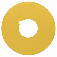
Background Label
Manufacturer
Omron
Type
Emergency Stop Switchr
Datasheets
1.M165-TG-24D.pdf
(45 pages)
2.A165E-S-02.pdf
(10 pages)
3.A16Z-5070.pdf
(12 pages)
4.A16Z-5070.pdf
(7 pages)
Specifications of A16Z-5070
Accessory Type
Emergency Stop Name Plate
Label Size
45mm Dia
Colour
Yellow Name Plate
Legend
Blank
Svhc
No SVHC (15-Dec-2010)
Color
Yellow
Lead Free Status / RoHS Status
Lead free / RoHS Compliant
For Use With
A16 Series Switches
For Use With/related Products
A16 Series Emergency Stop Switches
Lead Free Status / Rohs Status
Lead free / RoHS Compliant
Other names
A16Z5070
Z1435
Z1435


Installation
■ Mounting to the Panel
After installing the Operation Unit, snap in the Switch from the back of the panel.
1. Installing the Switch
Attach rubber packing or the Yellow Plate onto the Switch from its terminal side. Insert the Switch into the panel from the front. Install the lock ring
and mounting nut from the terminal side and tighten.
Adjust the slits on the hole of rubber packing and Yellow Plate to the protruding part of the Unit.
Rubber packing is not necessary when the Yellow Plate is used.
Tighten the nut to the torque of 0.29 to 0.49 N·m.
Casing should be installed with its protruding part adjusted to the slit of the panel hole.
Align the lock ring to the groove of the casing so that the edge is drawn to the panel side.
2. Mounting the Switch
Snap on the Switch to the Operation Unit.
Make sure that the Switch has the correct orientation when snapping
it onto the Operation Unit. Align the white dot on the Operation Unit
with the guide groove on the side of the Switch marked with an “L” as
shown below, and push the Switch into the Operation Unit until it
clicks into place. Confirm that the Switch is securely in place before
using.
D-10
Emergency Stop Switch
Lock hole
Cutout
Lock
White dot
Guide groove
A165E
Mounting nut
Rubber packing
(included with the
product) or Yellow
Plate (sold separately)
Lock ring
Panel
L marking
3. Removing the Switch
Insert the prongs of the A16Z-5080 Extractor between the Switch
and the Operation Unit, grip the Switch, and pull to remove.
4. Installing the LED Lamp
When mounting the Lamp, make sure it is facing the direction shown
in the following diagram. Insert the Lamp while matching the
protruding part of the Lamp and the small guides on the outer
surface of the casing.
Rubber packing or Yellow Plate (sold separately)
Protruding part
Panel
Edge
Wide guide
Extractor
(A16Z-5080)
Mounting nut
Narrow guide
Lock ring
Related parts for A16Z-5070
Image
Part Number
Description
Manufacturer
Datasheet
Request
R

Part Number:
Description:
SCREEN FITTING
Manufacturer:
Omron
Datasheet:

Part Number:
Description:
NEON LAMP 110V RED FOR A16
Manufacturer:
Omron
Datasheet:

Part Number:
Description:
NEON LAMP 110V GREEN FOR A16
Manufacturer:
Omron
Datasheet:

Part Number:
Description:
SWTCH BLOCK SPDT SOLDER TERMINAL
Manufacturer:
Omron
Datasheet:

Part Number:
Description:
LAMP INCAND 6VAC/DC 16 SERIES
Manufacturer:
Omron
Datasheet:

Part Number:
Description:
CASE ROUND 16 SERIES MOMENTARY
Manufacturer:
Omron
Datasheet:

Part Number:
Description:
LAMP LED 6VAC/DC 16 SERIES RED
Manufacturer:
Omron
Datasheet:

Part Number:
Description:
LAMP LED 5VDC YLW FOR A16 SWITCH
Manufacturer:
Omron
Datasheet:

Part Number:
Description:
SWTCH BLOCK DPDT SOLDER TERMINAL
Manufacturer:
Omron
Datasheet:

Part Number:
Description:
SWTCH BLOCK SPDT PCB TERMINAL
Manufacturer:
Omron
Datasheet:

Part Number:
Description:
SWITCH PB SQUARE MOM SPDT GREEN
Manufacturer:
Omron
Datasheet:
Part Number:
Description:
SWITCH PB SQUARE MOM SPDT WHITE
Manufacturer:
Omron
Datasheet:
Part Number:
Description:
SWITCH PB SQUARE MOM SPDT YELLOW
Manufacturer:
Omron
Datasheet:
Part Number:
Description:
SWITCH PB RECTANG MOM SPDT BLUE
Manufacturer:
Omron
Datasheet:
Part Number:
Description:
SWITCH PB RECTANG MOM SPDT YEL
Manufacturer:
Omron
Datasheet: