ITP120 Fluke Electronics, ITP120 Datasheet
ITP120
Manufacturer Part Number
ITP120
Description
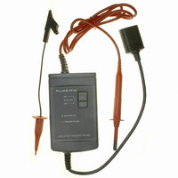
ISOLATED TRIGGER PROBE
Manufacturer
Fluke Electronics
Series
ScopeMeter® 120r
Type
Trigger Probe, Optically Isolatedr
Datasheet
1.ITP120.pdf
(2 pages)
Specifications of ITP120
Includes
Battery, Ground Lead with Hook
Bandwidth
50kHz
Resistance - Input
10M
Voltage - Max
CAT II 600VRMS
Capacitance - Input
15pF
Cable Length
48.000" (1219.20mm)
Color
Gray
Lead Free Status / RoHS Status
Contains lead / RoHS non-compliant
Attenuation Value
-
Other names
614-1117


Introduction
The ITP 120 is an optically isolated trigger probe for
isolated trigger purposes with the Fluke 120 series
ScopeMeter test tool.
Specifications
Probe Characteristics
Maximum floating voltage to ground: 600V
Maximum input voltage: 600V (with 600V Mini
Maximum non-destructive input voltage times
Input resistance: 10 MΩ ± 1%
Input capacitance: 15 pF ± 10%
Probe length: 1.2 m (48 inch)
Trigger Characteristics
Trigger level: TTL compatible (High ≥ 2V, Low ≤ 0.8V)
Minimum pulsewidth: 7 µs
Frequency range: DC to 50 kHz
Trigger slope selectable on the ScopeMeter test tool.
Battery Type: Alkaline 9 volt, NEDA, IEC6LR61
Battery Life: 60 hour operation
June 1996, Rev. 2, 4/97
© 1996, 1997 Fluke
Corporation.
All rights reserved.
Printed in The Netherlands.
All product names are trademarks of their respective companies
frequency: 10
Isolated Trigger Probe
9
Testhook)
Instruction Sheet
ITP 120
®
Environmental Specifications
Meet requirements of:
This product is in conformity with Electromagnetic
Compatibility Directive 89/336/EEC, and Low Voltage
Directive 73/23/EEC.
This conformity is indicated by the symbol
“Conformité européenne”
Temperature:
Operating: 0 °C to +50 °C (32 °F to +122 °F)
Non-operating: -40 °C to +70 °C (-40 °F to +158 °F)
Meets requirements of:
•
•
Unpacking
Check that the following items are included with the
ITP 120:
•
•
•
Using the ITP 120
•
•
•
Safety
UL 3111
IEC1010-2-031 CAT II 600V
Trigger Probe
Mini Testhook (with ground lead)
9V Battery (installed)
MIL-T-28800E, Type III, Class 3
EN 50081-1, Electromagnetic Compatibility
Generic Emission Standard: EN55022 and
EN60555-2
EN 50082-1, Electromagnetic Compatibility
Generic Immunity Standard: IEC801-2, -3, -4, -5
(
Double Insulation)
, i.e.
Limited Warranty &
Limitation of Liability
This Fluke product will be free from defects in material
and workmanship for one year from the date of
purchase. This warranty does not cover fuses,
disposable batteries or damage from accident, neglect,
misuse or abnormal conditions of operation or
handling. Resellers are not authorized to extend any
other warranty on Fluke’s behalf. To obtain service
during the warranty period, send your defective product
to the nearest Fluke Authorized Service Center with a
description of the problem.
THIS WARRANTY IS YOUR ONLY REMEDY. NO
OTHER WARRANTIES, SUCH AS FITNESS FOR A
PARTICULAR PURPOSE, ARE EXPRESSED OR
IMPLIED. FLUKE IS NOT LIABLE FOR ANY SPECIAL,
INDIRECT, INCIDENTAL OR CONSEQUENTIAL
DAMAGES OR LOSSES, ARISING FROM ANY
CAUSE OR THEORY.
Since some states or countries do not allow the
exclusion or limitation of an implied warranty or of
incidental or consequential damages, this limitation of
liability may not apply to you.
Fluke Corporation
P.O. Box 9090
Everett WA 98206-9090
USA.
Service Centers
To locate an authorized service center, visit us on the
World Wide Web:
or call Fluke using any of the phone numbers listed
below:
http://www.fluke.com
+1-800-443-5853 in USA and Canada
+31-402-678-200 in Europe
+1-206-356-5500 from other countries
Fluke Industrial B.V.
P.O. Box 680
7600 AR Almelo
The Netherlands
ITP120 Summary of contents
Page 1
ITP 120 Isolated Trigger Probe Instruction Sheet Introduction The ITP 120 is an optically isolated trigger probe for isolated trigger purposes with the Fluke 120 series ScopeMeter test tool. Specifications Probe Characteristics Maximum floating voltage to ground: 600V Maximum input ...
Page 2
... Not OK: replace item 1. } -2.5...-2.5V OK: check 3* for pulses OK: replace item 1. Not OK: replace item 11. Trigger slope error: D. Connect ITP120 to test tool Select +slope and check wire 1 for +1.2V Select - slope and check wire 1 for -2.5V OK: replace item 11. Not OK: replace item ITEM ORDERING CODE ...