B59601A0095A062 EPCOS Inc, B59601A0095A062 Datasheet - Page 20
B59601A0095A062
Manufacturer Part Number
B59601A0095A062
Description
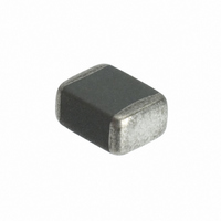
THERMISTOR PTC 470OHM 95DEG 0603
Manufacturer
EPCOS Inc
Series
B59601r
Type
PTCr
Specifications of B59601A0095A062
Package / Case
0603 (1608 Metric)
Resistance In Ohms @ 25°c
470
Resistance Tolerance
±50%
Mounting Type
Non-Standard, Leadless
Thermistor Type
PTC
Resistance
470ohm
Svhc
No SVHC (18-Jun-2010)
Body Diameter
0.8mm
External Length / Height
1.6mm
Operating Voltage
32V
Resistance Temperature
-40°C
Termination Style
SMD/SMT
Lead Free Status / RoHS Status
Lead free / RoHS Compliant
Operating Temperature
-
Power - Max
-
Lead Free Status / Rohs Status
Lead free / RoHS Compliant
Other names
495-2410-2
B59601A 95A 62
B59601A95A62
B59601A 95A 62
B59601A95A62
Available stocks
Company
Part Number
Manufacturer
Quantity
Price
Company:

Part Number:
B59601A0095A062
Manufacturer:
TDK-EPCOS
Quantity:
84 000
Part Number:
B59601A0095A062
Manufacturer:
EPCOS/爱普科斯
Quantity:
20 000


Do not store SMDs where they are exposed to heat or direct sunlight. Otherwise, the packing ma-
terial may be deformed or SMDs may stick together, causing problems during mounting.
After opening the factory seals, such as polyvinyl-sealed packages, it is recommended to use the
components as soon as possible.
3
An alternative to soldering is the gluing of thermistors with conductive adhesives. The benfit of
this method is that it involves no thermal stress. The adhesives used must be chemically inert and
suitable for the temperatures arising at the surface of the termistor.
4
Pressure contacting by springs is required for applications involving frequent switching and high
turn-on powers. Soldering is not allowed for such applications in order to avoid operational failure
in the long term. PTC thermistors for heating and motor starting have metallized surfaces for
clamp contacting.
5
The leads meet the requirements of IEC 60068-2-21. They may not be bent closer than 4 mm
from the solder joint on the thermistor body or from the point at which they leave the
feedthroughs. During bending, any mechanical stress at the outlet of the leads must be removed.
The bending radius should be at least 0.75 mm.
Tensile strength:
Bending strength: Test Ub:
Torsional strength: Test Uc: severity 2
Please read Cautions and warnings and
Important notes at the end of this document.
Sensors
Limit temperature sensors, EIA sizes 0603 and 0805
Conductive adhesion
Clamp contacting
Robustness of terminations
Test Ua1:
Leads
Two 90 -bends in opposite directions at a weight of 0.25 kg.
The lead is bent by 90 at a distance of 6 to 6.5 mm from the thermistor body.
The bending radius of the leads should be approx. 0.75 mm. Two torsions of
180 each (severity 2).
> 0.5 mm = 10 N
0.5 mm = 5 N
Page 20 of 26
Standard series
Related parts for B59601A0095A062
Image
Part Number
Description
Manufacturer
Datasheet
Request
R

Part Number:
Description:
THERMISTOR PTC 470OHM 115DEG0603
Manufacturer:
EPCOS Inc
Datasheet:


Part Number:
Description:
CAP .15UF 63V METAL POLY
Manufacturer:
EPCOS Inc
Datasheet:


Part Number:
Description:
CAP .01UF 400V METAL POLY
Manufacturer:
EPCOS Inc
Datasheet:
