YGM1 C511 Cantherm, YGM1 C511 Datasheet - Page 2
YGM1 C511
Manufacturer Part Number
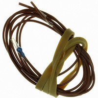
YGM1 C511
Description
THERM PTC MINI-BEAD 3MM 110C
Manufacturer
Cantherm
Series
YGMr
Datasheet
1.YGM1_C517.pdf
(4 pages)
Specifications of YGM1 C511
Resistance In Ohms @ 25°c
250
Resistance Tolerance
±10%
Operating Temperature
-20°C ~ 60°C
Power - Max
690mW
Mounting Type
PCB, Through Hole
Package / Case
Radial
Lead Free Status / RoHS Status
Lead free / RoHS Compliant
Other names
317-1113


OPERATION
PTC thermistors exhibit very high sensitivity over a
narrow temperature band. For temperature measure-
ment in this range, NTC thermistors are easier to
measure and more accurate.
PTC thermistors are especially suited as temperature
sensors for monitoring the windings of electric
machines, and also for use in simple fail-safe circuitry.
When a given temperature (nominal response tempe-
rature
off through a relay or amplifier, since the PTC-sensor
will have an extremely high ohmic value in the region
of its response temperature. This will have the same
effect as a break in the circuit or a failure of the
thermistor.
TECHNICAL DATA
Nominal response temperature
Maximum allowable operating temp.
Max. allowable operating voltage at + 25 °C
Max. allowable power dissipation at + 25 °C
Insulation strength (between leads and outer insulation)
also for threaded sensor
Conductors - silvered copper wire with teflon insulation
Insulation stripping
Conductor cross-section
CONDUCTOR LENGTHS
Single PTC
Double PTC
Triple PTC
SPECIAL VERSIONS
PTC’s are also available in many special housings
(can be manufactured to customers specifications)
INSTALLATION TIPS
For PTC temperature sensors in electrical windings:
- the thermistors can only be inserted in the windings
- it is advisable to embed one in each phase, if
- air inflow onto the temperature sensor will interfere
- if using varnish/lacquer which is not chemically
- WARNING! It is very important that the sensor must
before impregnation
possible in the centre of the coil generating most
heat, and generally on the outflow side of any air
movement
with heat transfer
neutral, suitability tests must be undertaken by the
customer
be installed parallel with the copper of the winding,
so that the teflon leads can assume the form of the
rest of the winding and thereby retain the high-
voltage resistance rating.
NAT
) is exceeded, the circuit can be switched
500 mm
500 - 180 - 500 m
500 - 180 - 180 - 500 mm
of 10 °, plus 145 ° and 155 °C
0.25 mm
10 mm
80 ° to 180 °C in steps
U
2
max.
for single, double
10 mm
and triple PTC’s
25V (per bead)
approx 10 mm
T
max.
10 mm
690 mW
200 °C
2.5 kV
PTFE
- PTC’s are classified according to their nominal
STANDARD RESISTANCE VALUES
Single PTC
Temperature
°C
– 20 to
Triple PTC
Temperature
°C
– 20 to
* one PTC might reach
The PTC’s resistance values for motor protection are
specified in DIN 44081/44082. Resistance values
below
when cold is no indication of the PTC’s condition. It is
ideally between 40 - 200 ohms but can be anywhere
between 35 - 250 ohms.
The greatest resistance change occurs between
Twin/double and triple PTC’s are available with
standard or mini-bead.
QUALITY STANDARD
Random testing is carried out according to DGQ
P90/P10 (DIN 40080). AQL values can be fixed by
arrangement.
ORDERING INFORMATION
of the others could still remain at room temperature.
response temperature
resistance characteristics to simplify the choice
of switching device; the relationship of resistance
to temperature of all these PTC’s is as follows:
NAT
NAT
NAT
NAT
NAT
NAT
NAT
5 °C either side of
Quantity
– 5
+ 5
+ 15
– 5
+ 5
+ 15
1.000
NAT
NAT
NAT
– 20
– 20
–20 are not specified, and resistance
Type
YD1
NAT
NAT
+ 15 °C, while the second or even both
Resistance
1.000
1.330 min.
4.000 min
Resistance
1.650 max.
4.000 min.
4.000 min.*
, being at least 15%/K.
250 max./100 max.
550 max.
750 max./300 max.
NAT
but all have similar
Temperature
code No.
C 510
measuring Voltage
measuring Voltage
Resistance
250 ohms
max.
2.5
2.5
2.5
2.5
7.5
7.5
7.5
7.5
7.5
V
V
Related parts for YGM1 C511
Image
Part Number
Description
Manufacturer
Datasheet
Request
R

Part Number:
Description:
THERM PTC MINI-BEAD 3MM 170C
Manufacturer:
Cantherm
Datasheet:

Part Number:
Description:
THERM PTC MINI-BEAD 3MM 120C
Manufacturer:
Cantherm
Datasheet:

Part Number:
Description:
THERM PTC MINI-BEAD 3MM 90C
Manufacturer:
Cantherm
Datasheet:

Part Number:
Description:
THERM PTC MINI-BEAD 3MM 80C
Manufacturer:
Cantherm
Datasheet:

Part Number:
Description:
THERM PTC MINI-BEAD 3MM 100C
Manufacturer:
Cantherm
Datasheet:

Part Number:
Description:
THERM PTC MINI-BEAD 3MM 130C
Manufacturer:
Cantherm
Datasheet:

Part Number:
Description:
THERM PTC MINI-BEAD 3MM 140C
Manufacturer:
Cantherm
Datasheet:

Part Number:
Description:
THERM PTC MINI-BEAD 3MM 145C
Manufacturer:
Cantherm
Datasheet:
Part Number:
Description:
THERM PTC MINI-BEAD 3MM 150C
Manufacturer:
Cantherm
Datasheet:

Part Number:
Description:
THERM PTC MINI-BEAD 3MM 155C
Manufacturer:
Cantherm
Datasheet:

Part Number:
Description:
THERM PTC MINI-BEAD 3MM 160C
Manufacturer:
Cantherm
Datasheet:

Part Number:
Description:
THERM PTC MINI-BEAD 3MM 180C
Manufacturer:
Cantherm
Datasheet:

Part Number:
Description:
CURRENT LIMITOR INRUSH 10OHM 20%
Manufacturer:
Cantherm
Datasheet:

Part Number:
Description:
CURRENT LIMITER INRUSH 10OHM 20%
Manufacturer:
Cantherm
Datasheet:

Part Number:
Description:
CURRENT LIMITER INRUSH 10OHM 20%
Manufacturer:
Cantherm
Datasheet: