NTHS0805N11N2202JE Vishay, NTHS0805N11N2202JE Datasheet - Page 19
NTHS0805N11N2202JE
Manufacturer Part Number
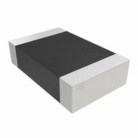
NTHS0805N11N2202JE
Description
THERMISTOR NTC 22K OHM 5% 0805
Manufacturer
Vishay
Series
NTHSr
Type
NTCr
Datasheets
1.S29GL032N90TFI010.pdf
(81 pages)
2.NTHS0603N02N1002KE.pdf
(3 pages)
3.NTHS0805N11N2202JE.pdf
(3 pages)
Specifications of NTHS0805N11N2202JE
Resistance In Ohms @ 25°c
22K
Resistance Tolerance
±5%
B Value Tolerance
±3%
B25/75
3700K
Mounting Type
Surface Mount
Package / Case
0805 (2012 Metric)
Description Of Terminals
Leadless
Mounting Style
Surface Mount
Pin Count
2
Screening Level
Automotive
Sensitivity Index
3700K
Resistance @ 25c
22kohm
Percentage Of Resistance Tolerance @ 25c
±5
Accuracy
±3
Operating Temperature Min Deg. C
-40C
Operating Temperature Max Deg. C
125C
Product Length (mm)
2mm
Product Depth (mm)
1.25mm
Lead Free Status / RoHS Status
Lead free by exemption / RoHS Compliant
B0/50
-
B25/50
-
B25/85
-
B25/100
-
Operating Temperature
-
Power - Max
-
Lead Length
-
Lead Free Status / Rohs Status
Lead free / RoHS Compliant
Other names
541-1139-2
Available stocks
Company
Part Number
Manufacturer
Quantity
Price

Part Number:
NTHS0805N11N2202JE
Manufacturer:
VISHAY/威世
Quantity:
20 000


8.4
8.5
8.6
8.7
October 29, 2008 S29GL-N_01_12
Standby Mode
Automatic Sleep Mode
RESET#: Hardware Reset Pin
Output Disable Mode
When the system is not reading or writing to the device, it can be placed in to standby mode. In this mode,
current consumption is greatly reduced, and the outputs are placed in the high impedance state, independent
of the OE# input.
The device enters the CMOS standby mode when the CE# and RESET# pins are both held at V
(Note that this is a more restricted voltage range than V
V
standard access time (t
it is ready to read data.
If the device is deselected during erasure or programming, the device draws active current until the operation
is completed.
Refer to the
The automatic sleep mode minimizes Flash device energy consumption. The device automatically enables
this mode when addresses remain stable for t
CE#, WE#, and OE# control signals. Standard address access timings provide new data when addresses are
changed. While in sleep mode, output data is latched and always available to the system. Refer to the
Characteristics on page 62
The RESET# pin provides a hardware method of resetting the device to reading array data. When the
RESET# pin is driven low for at least a period of t
progress, output pins go to Hi-Z, and all read/write commands are ignored for the duration of the RESET#
pulse. Program/Erase operations that were interrupted should be reinitiated once the device is ready to
accept another command sequence, to ensure data integrity.
Current is reduced for the duration of the RESET# pulse. When RESET# is held at V
draws CMOS standby current (I
The RESET# pin may be tied to the system reset circuitry. A system reset would thus also reset the Flash
memory, enabling the system to read the boot-up firmware from the Flash memory.
Refer to the AC Characteristics tables for RESET# parameters and to
diagram.
When the OE# input is at V
impedance state.
IO
± 0.3 V, the device is in the standby mode, but the standby current is greater. The device requires
DC Characteristics on page 62
ACC
D a t a
/t
IH
for the automatic sleep mode current specification.
CE
, output from the device is disabled. The output pins are placed in a high
S29GL-N MirrorBit
) for read access when the device is in either of these standby modes, before
CC5
S h e e t
).
for the standby current specification.
ACC
®
Flash Family
RP
+ 30 ns. The automatic sleep mode is independent of the
, the device immediately terminates any operation in
IH
.) If CE# and RESET# are held at V
Figure 15.4 on page 66
SS
±0.3 V, the device
IH
, but not within
for the timing
IO
± 0.3 V.
DC
19
Related parts for NTHS0805N11N2202JE
Image
Part Number
Description
Manufacturer
Datasheet
Request
R

Part Number:
Description:
Manufacturer:
Vishay
Datasheet:
Part Number:
Description:
357-036-542-201 CARDEDGE 36POS DL .156 BLK LOPRO
Manufacturer:
Vishay
Datasheet:
Part Number:
Description:
357-036-542-201 CARDEDGE 36POS DL .156 BLK LOPRO
Manufacturer:
Vishay
Datasheet:
Part Number:
Description:
357-036-542-201 CARDEDGE 36POS DL .156 BLK LOPRO
Manufacturer:
Vishay
Datasheet:
Part Number:
Description:
357-036-542-201 CARDEDGE 36POS DL .156 BLK LOPRO
Manufacturer:
Vishay
Datasheet:
Part Number:
Description:
357-036-542-201 CARDEDGE 36POS DL .156 BLK LOPRO
Manufacturer:
Vishay
Datasheet:
Part Number:
Description:
357-036-542-201 CARDEDGE 36POS DL .156 BLK LOPRO
Manufacturer:
Vishay
Datasheet:
Part Number:
Description:
357-036-542-201 CARDEDGE 36POS DL .156 BLK LOPRO
Manufacturer:
Vishay
Datasheet:
Part Number:
Description:
357-036-542-201 CARDEDGE 36POS DL .156 BLK LOPRO
Manufacturer:
Vishay
Datasheet:
Part Number:
Description:
357-036-542-201 CARDEDGE 36POS DL .156 BLK LOPRO
Manufacturer:
Vishay
Datasheet:
Part Number:
Description:
357-036-542-201 CARDEDGE 36POS DL .156 BLK LOPRO
Manufacturer:
Vishay
Datasheet:
Part Number:
Description:
357-036-542-201 CARDEDGE 36POS DL .156 BLK LOPRO
Manufacturer:
Vishay
Datasheet:
Part Number:
Description:
357-036-542-201 CARDEDGE 36POS DL .156 BLK LOPRO
Manufacturer:
Vishay
Datasheet:
Part Number:
Description:
357-036-542-201 CARDEDGE 36POS DL .156 BLK LOPRO
Manufacturer:
Vishay
Datasheet:
Part Number:
Description:
357-036-542-201 CARDEDGE 36POS DL .156 BLK LOPRO
Manufacturer:
Vishay
Datasheet: