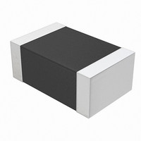
NTCS0805E3104GXT Vishay, NTCS0805E3104GXT Datasheet - Page 7

NTCS0805E3104GXT
Manufacturer Part Number
NTCS0805E3104GXT
Description
THERMISTOR NTC 100K OHM SMD 0805
Manufacturer
Vishay
Type
NTCr
Specifications of NTCS0805E3104GXT
Resistance In Ohms @ 25°c
100K
Resistance Tolerance
±2%
B Value Tolerance
±1%
B25/85
4100K
Operating Temperature
-40°C ~ 150°C
Power - Max
210mW
Mounting Type
Surface Mount
Package / Case
0805 (2012 Metric)
Description Of Terminals
Leadless
Mounting Style
Surface Mount
Pin Count
2
Screening Level
Automotive
Sensitivity Index
4100K
Resistance @ 25c
100kohm
Thermal Time Constant
10s
Percentage Of Resistance Tolerance @ 25c
±2
Accuracy
±1
Operating Temperature Min Deg. C
-40C
Operating Temperature Max Deg. C
150C
Product Length (mm)
2mm
Product Height (mm)
0.8mm
Product Depth (mm)
1.25mm
Lead Free Status / RoHS Status
Lead free / RoHS Compliant
B0/50
-
B25/50
-
B25/75
-
B25/100
-
Lead Length
-
Lead Free Status / Rohs Status
Lead free / RoHS Compliant
Other names
BC2563TR
Available stocks
Company
Part Number
Manufacturer
Quantity
Price
Part Number:
NTCS0805E3104GXT
Manufacturer:
VISHAY/威世
Quantity:
20 000
SOLDERING CONDITIONS
This SMD thermistor is only suitable for wave or reflow soldering, in accordance with JEDEC J-STD-020. The maximum
temperature of 260 °C during 40 seconds should not be exceeded.
Typical examples of a soldering processes that will provide reliable joints without damage, are shown below.
TESTS AND REQUIREMENTS
PACKAGING
TAPE SPECIFICATIONS
All tape specifications are in accordance with
PAPER TAPE
Document Number: 29044
Revision: 26-May-10
SOLDERABILITY AND RESISTANCE TO SOLDERING HEAT
IEC 60068-2-58
300
250
200
150
100
50
0
6
D 0
0
≈ 245 °C
260 °C
215 °C
180 °C
130 °C
A 0
50
B 0
P 1
P 2
Reflow Soldering
TEST METHOD
2 K/s
P 0
100
TC
Time (s)
150
For technical questions, contact:
10 s
10 s
1.3
40 s
Resistance to soldering heat
F
E 1
SMD 0805, Glass Protected
“IEC 60286-3”
200
W
Dimensions of the solder lands
Solderability
NTC Thermistors
1.0
TEST
T 1
T
250
. Basic dimensions are given below. Carrier tape material is paper.
3.0
Notes
(1)
(2)
NTCS0805E3.....T/2381 615 5....
PAPER TAPE DIMENSIONS in millimeters
PARAMETER
A
B
W
E
F
D
P
P
P
T tape thickness
T
Measured 0.3 mm above base pocket
P
1
0
0
1
0
1
2
0
0
nlr@vishay.com
(1)
(1)
(2)
cover tape
pitch cumulative error over any 10 pitches ± 1.0 mm
300
250
200
150
100
50
0
0
PROCEDURE
10 s at 260 °C
Lead (Pb)-free Reflow Soldering Profile
2 s at 235 °C
≈ 245 °C
≈ 170 °C
235 °C
260 °C
50
100
2 K/s
max.
Vishay BCcomponents
≈ 120 °C
DIMENSION
150
Time (s)
< 0.1
2.35
1.75
1.55
1.7
8.0
3.5
4.0
4.0
2.0
1.1
Min. 95 % of surface wetted
200
REQUIREMENTS
ΔR/R < 5 %
250
20 s min.
40 s max.
≈ 60 s
TOLERANCE
www.vishay.com
6 K/s
max.
limit
normal
300
± 0.05
± 0.05
± 0.05
± 0.2
± 0.1
± 0.2
± 0.1
± 0.1
± 0.1
max.
-
350
33


