AD592BN Analog Devices Inc, AD592BN Datasheet - Page 8
AD592BN
Manufacturer Part Number
AD592BN
Description
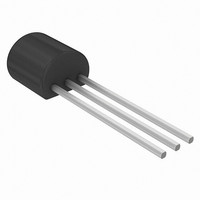
IC TEMP TRANSDUCER 2-TERM TO92-3
Manufacturer
Analog Devices Inc
Datasheet
1.DF36022FPV.pdf
(8 pages)
Specifications of AD592BN
Rohs Status
RoHS non-compliant
Sensing Temperature
-25°C ~ 105°C
Output Type
Current
Voltage - Supply
4 V ~ 30 V
Accuracy
±0.7°C
Package / Case
TO-226-3, TO-92-3 (TO-226AA)
Peak Reflow Compatible (260 C)
No
Ic Function
Temperature Sensor IC
Termination Type
Through Hole
Leaded Process Compatible
No
Mounting Type
Through Hole
Operating Temperature Range
-25°C To +105°C
Lead Free Status / RoHS Status
Contains lead / RoHS non-compliant
Available stocks
Company
Part Number
Manufacturer
Quantity
Price

Company:
Part Number:
AD592BN
Manufacturer:
PMI
Quantity:
5 510
Company:
Part Number:
AD592BNZ
Manufacturer:
RENESAS
Quantity:
12 000


AD592
To minimize the number of MUXs required when a large num-
ber of AD592s are being used, the circuit can be configured in a
matrix. That is, a decoder can be used to switch the supply volt-
age to a column of AD592s while a MUX is used to control
which row of sensors are being measured. The maximum num-
ber of AD592s which can be used is the product of the number
of channels of the decoder and MUX.
An example circuit controlling 80 AD592s is shown in Figure
16. A 7-bit digital word is all that is required to select one of
the sensors. The enable input of the multiplexer turns all the
sensors off for minimum dissipation while idling.
+15V
4028 BCD TO DECIMAL DECODER
Figure 16. Matrix Multiplexer
80 – AD592s
COLUMN
SELECT
Dimensions shown in inches and (mm).
SEATING
SELECT
ROW
PLANE
0.105 (2.66)
0.080 (2.42)
OUTLINE DIMENSIONS
0.105 (2.66)
0.080 (2.42)
E
0.105 (2.66)
0.095 (2.42)
N
(3.43)
0.135
MIN
(12.70)
+15V
–15V
0.500
MIN
V
10k
OUT
BOTTOM VIEW
1
–8–
2
To convert the AD592 output to C or F a single inexpensive
reference and op amp can be used as shown in Figure 17. Al-
though this circuit is similar to the two temperature trim circuit
shown in Figure 6, two important differences exist. First, the
gain resistor is fixed alleviating the need for an elevated tem-
perature trim. Acceptable accuracy can be achieved by choosing
an inexpensive resistor with the correct tolerance. Second, the
AD592 calibration error can be trimmed out at a known conve-
nient temperature (i.e., room temperature) with a single pot ad-
justment. This step is independent of the gain selection.
AD1403
3
0.055 (1.39)
0.045 (1.15)
0.210 (5.33)
0.170 (4.32)
0.165 (4.19)
0.125 (3.94)
0.019 (0.482)
0.016 (0.407)
0.205 (5.20)
0.175 (4.96)
Figure 17. Celsius or Fahrenheit Thermometer
SQUARE
0.050
(1.27)
MAX
+5V
2.5V
R
OFFSET
R
R
OFFSET
/R
GAIN
R
CAL
V–
AD592
R
GAIN
AD741
V
OUT
= 100mV/(
o
o
C
F
R
o
C OR
OFFSET
9.1k
9.8k
o
F)
REV. A
R
100k
180k
GAIN
Related parts for AD592BN
Image
Part Number
Description
Manufacturer
Datasheet
Request
R

Part Number:
Description:
±1.7g Dual-Axis IMEMS Accelerometer Evaluation Board
Manufacturer:
Analog Devices Inc
Datasheet:

Part Number:
Description:
Inertial Sensor Evaluation System
Manufacturer:
Analog Devices Inc
Datasheet:
Part Number:
Description:
Manufacturer:
Analog Devices Inc
Datasheet:
Part Number:
Description:
Manufacturer:
Analog Devices Inc
Datasheet:
Part Number:
Description:
Manufacturer:
Analog Devices Inc
Datasheet:
Part Number:
Description:
Manufacturer:
Analog Devices Inc
Datasheet:
Part Number:
Description:
Manufacturer:
Analog Devices Inc
Datasheet:
Part Number:
Description:
Manufacturer:
Analog Devices Inc
Datasheet:
Part Number:
Description:
Manufacturer:
Analog Devices Inc
Datasheet:
Part Number:
Description:
Manufacturer:
Analog Devices Inc
Datasheet:
Part Number:
Description:
Manufacturer:
Analog Devices Inc
Datasheet:
Part Number:
Description:
Manufacturer:
Analog Devices Inc
Datasheet:
Part Number:
Description:
Manufacturer:
Analog Devices Inc
Datasheet: