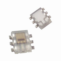
TPS852(T) Toshiba, TPS852(T) Datasheet

TPS852(T)
Specifications of TPS852(T)
TPS852TR
TPS852TR
TPS852TTR
Related parts for TPS852(T)
TPS852(T) Summary of contents
Page 1
... Please design the appropriate reliability upon reviewing the Toshiba Semiconductor Reliability Handbook (“Handling Precautions”/“Derating Concept and Methods”) and individual reliability data (i.e. reliability test report and estimated failure rate, etc) ...
Page 2
Electrical and Optical Characteristics Characteristics Supply voltage Supply current Light current (1) Light current (2) Light current (3) Light current ratio Dark current Saturation output voltage Peak sensitivity wavelength Rise time Fall time Switching time Delay time Storage time Note ...
Page 3
Package Dimensions 3 0.20 0.3Typ. Weight: 0.003 g (typ.) Block Diagram 0.50 0.50 1.60 5 ° Current amp 6. OUT 2. GND 3. GND 4. GND 5. GND 3 TPS852 Unit: mm Tolerance: ...
Page 4
Handling Precautions When Vcc is turned on it takes at least 200 ms for the internal circuit to stabilize. During this time the output signal is unstable. Please do not use the unstable signal as the output signal. Moisture-Proof Packing ...
Page 5
Recommended soldering pattern (3) Cleaning conditions When cleaning is required after soldering Chemicals: AK225 alcohol Temperature and time: 50°C × 30°C × 3 mins Ultrasonic cleaning: 300 W or less Packing Specification (1) Packing quantity Reel ...
Page 6
Tape Packing Specifications (1) Reel dimensions Reel material: Plastic 5.0 5.0 11.4 9.0 Enlarged view of reel center 2 ± 0.5 6 TPS852 Unit: mm φ 21 ± 0.8 120° φ 13 ± 0.2 2007-10-01 ...
Page 7
Tape dimensions Tape material: Plastic (anti-electrostatic) 4.0±0.1 + 0.1 φ 1.5 − 0 2.0±0.05 φ 1.1±0.1 4.0±0.1 max 6 ° A Product direction 1.7 ± 0.1 max 6 ° TPS852 Unit: mm 0.25 ...
Page 8
Reel Label The label markings may include product number, tape type and quantity. P/N TYPE TPS852 ADDC Q’TY NOTE Leader and Trailer Sections of Tape Note 1 : The leader portion shell consist of cover tape minimum length of 300 ...
Page 9
P – Ambient temperature Ta (°C) I – 10000 1000 100 25° light ...
Page 10
I – 1000 100 25° using A light source 5.1 kΩ kΩ 100 kΩ 0 100 ...
Page 11
Switching Time Measurement Circuit and Waveforms Pulse drive White LED Spectral Response 100 Ta = 25° 200 400 600 800 Wavelength λ (nm TPS852 OUT R L GND (typ.) Luminosity angle 40° 50° ...
Page 12
... Product shall not be used for or incorporated into any products or systems whose manufacture, use, or sale is prohibited under any applicable laws or regulations. • The information contained herein is presented only as guidance for Product use. No responsibility is assumed by TOSHIBA for any infringement of patents or any other intellectual property rights of third parties that may result from the use of Product. No license to any intellectual property right is granted by this document, whether express or implied, by estoppel or otherwise. • ...


