AMS104W Panasonic Electric Works, AMS104W Datasheet - Page 9
AMS104W
Manufacturer Part Number
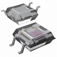
AMS104W
Description
SENSOR LIGHT NAPICA 6V SMD
Manufacturer
Panasonic Electric Works
Datasheet
1.AMS104W.pdf
(10 pages)
Specifications of AMS104W
Wavelength
580nm
Output Type
Analog
Package / Case
Surface Mount
Lead Free Status / RoHS Status
Lead free / RoHS Compliant
Other names
255-2654-2


Light Sensor (AMS3)
SAFETY PRECAUTIONS
Be sure to obey the following in order to prevent injuries and accidents.
• Do not use the sensors under conditions that exceed the range of its specifications.
• Connect terminals correctly by verifying the pin layout with the specifications diagram or other instructions.
• For an impotant and serious application in terms of safety, add protection circuit or any other protection method.
CAUTIONS FOR USE
1. Applying stress that exceeds the
absolute maximum rating
If the voltage or current value for any of
the terminals exceeds the absolute
maximum rating, internal elements will
deteriorate because of the excessive
voltage or current.
In extreme cases, wiring may melt, or
silicon P/N junctions may be destroyed.
As a result, the design should ensure that
the absolute maximum ratings will never
be exceeded, even momentarily.
2. Deterioration and destruction
caused by discharge of static
electricity
This phenomenon is generally called
static electricity destruction.
Static electricity generated by various
factors flows through the terminal and
occurs to destroy internal elements.
To prevent problems from static
electricity, the following precautions and
measures should be taken when using
your device.
1) Employees handling sensor should
wear anti-static clothing and should be
grounded through protective resistance
of 500 kΩ to 1 MΩ.
2) A conductive metal sheet should be
placed over the work table. Measuring
instruments and jigs should be grounded.
3) When using soldering irons, either use
irons with low leakage current, or ground
the tip of the soldering iron.
(Use of low-voltage soldering irons is also
recommended.)
4) Devices and equipment used in
assembly should also be grounded.
5) When packing printed circuit boards
and equipment, avoid using high-polymer
materials such as foam styrene, plastic,
and other materials which carry an
electrostatic charge.
6) When storing or transporting sensor,
the environment should not be generated
static electricity (for instance, the
humidity should be between 45 and
60%), and sensor should be protected
using conductive packing materials.
3. Just after supplying voltage, please
note that current in the sensor will be
not constant until internal circuit
stability.
It may cause overheating, smoke, or fire.
Erroneous connections may lead to unexpected operating errors, overheating, smoke, or fire.
All Rights Reserved © COPYRIGHT Matsushita Electric Works, Ltd.
4. Storage
The sensors are transparent plastic
packages. They are sensitive to moisture
and come in moisture-proof packages.
Observe the following cautions when
storing.
1) After the moisture-proof package is
unsealed, take the sensors out of storage
as soon as possible (within 1 week at the
most).
2) If the devices are to be left in storage
for a considerable period after the
moisture-proof package has been
unsealed, it is recommended to keep
them in another moisture-proof bag
containing silica gel (within 3 months at
the most).
3) Storage under extreme conditions will
cause soldering degradation, external
appearance defects, and deterioration of
the characteristics.
The following storage conditions are
recommended:
• Temperature: 0 to 30°C
• Humidity: Less than 60% R.H. (Avoid
freezing and condensing)
• Atomosphere: No harmful gasses such
as sulfurous acid gas, minimal dust.
* When mounting with solder, if thermal
stress is applied to sensors that have
absorbed moisture, the moisture will
vaporize, swelling will occur, and the
inside of the package will become
stressed.
This may cause the package surface to
blister or crack. Therefore, please take
caution and observe the soldering
conditions in the following section.
5. Recommended soldering
conditions
1) Recommended condition
(1) Double wave soldering method
T
T
t
t
1
2
1
2
+t
= 120 s or less
= 120°C
= 260°C
3
T
T
= 6 s or less
2
1
248°F
500°F
t
1
or less
32 to 86°F
t
2
t
3
(2) Soldering iron method
Tip temperature: 350 to 400°C
752°F
Wattage: 30 to 60 W
Soldering time: within 3 s
2) The soldered position on leads should
not be closer than 3mm
molding resin of this sensor.
6. Notes for mounting
1) Temperature rise in the lead portion is
highly dependent on package size.
If multiple different packages are
mounted on the same board, please
check your board beforehand in an actual
product, ensuring that the temperature of
the solder area of the sensor terminals
falls within the temperature conditions of
item 5.
2) If the mounting conditions exceed the
recommended solder conditions in item
5, resin strength will fall and the
mismatching of the heat expansion
coefficient of each constituent material
will increase markedly, possibly causing
cracks in the package, disconnections of
bonding wires, and the like.
For this reason, please inquire with us
about whether this use is possible.
7. Cleaning solvents compatibility
We recommend dip cleaning with an
organic solvent for removal of solder flux
etc.
If you cannot avoid using ultrasonic
cleansing, please ensure that the
following conditions are met, and check
beforehand for defects.
• Frequency: 27 to 29 kHz
• Ultrasonic power:
• Cleaning time:
• Cleanser used: Asahiklin AK-225
• Other: Submerge in solvent in order to
Note: Applies to unit area ultrasonic
power for ultrasonic baths.
8. Transportation
Extreme vibration during transport will
warp the lead or damage the sensor.
Handle the outer and inner boxes with
care.
No greater than 0.25W/cm
No longer than 30 s
prevent the PCB and sensors from
being contacted directly by the
ultrasonic vibrations.
.118inch
2
662 to
to the
Related parts for AMS104W
Image
Part Number
Description
Manufacturer
Datasheet
Request
R

Part Number:
Description:
Manufacturer:
Panasonic Electric Works
Datasheet:
Part Number:
Description:
Manufacturer:
Panasonic Electric Works
Datasheet:

Part Number:
Description:
CONN SOCKET P4 .4MM 50POS SMD
Manufacturer:
Panasonic Electric Works
Datasheet:
Part Number:
Description:
CONN SOCKET .8MM 16POS SMD
Manufacturer:
Panasonic Electric Works
Datasheet:
Part Number:
Description:
CONN HEADER .8MM 16POS SMD
Manufacturer:
Panasonic Electric Works
Datasheet:
Part Number:
Description:
CONN SOCKET .8MM 20POS SMD
Manufacturer:
Panasonic Electric Works
Datasheet:
Part Number:
Description:
CONN SOCKET .8MM 20POS SMD
Manufacturer:
Panasonic Electric Works
Datasheet:
Part Number:
Description:
CONN HEADER .8MM 20POS SMD
Manufacturer:
Panasonic Electric Works
Datasheet:
Part Number:
Description:
CONN SOCKET .8MM 22POS SMD
Manufacturer:
Panasonic Electric Works
Datasheet:
Part Number:
Description:
CONN SOCKET .8MM 30POS SMD
Manufacturer:
Panasonic Electric Works
Datasheet:
Part Number:
Description:
CONN HEADER .8MM 30POS SMD
Manufacturer:
Panasonic Electric Works
Datasheet:
Part Number:
Description:
CONN SOCKET .8MM 30POS SMD
Manufacturer:
Panasonic Electric Works
Datasheet:
Part Number:
Description:
CONN SOCKET .8MM 30POS SMD
Manufacturer:
Panasonic Electric Works
Datasheet:
Part Number:
Description:
CONN HEADER .8MM 30POS SMD
Manufacturer:
Panasonic Electric Works
Datasheet:
Part Number:
Description:
CONN HEADER BRD/BRD .5MM 60POS
Manufacturer:
Panasonic Electric Works
Datasheet: