ADIS16405BMLZ Analog Devices Inc, ADIS16405BMLZ Datasheet - Page 13
ADIS16405BMLZ
Manufacturer Part Number
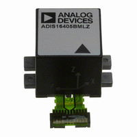
ADIS16405BMLZ
Description
MODULE GYRO/ACCEL/MAG 24ML
Manufacturer
Analog Devices Inc
Specifications of ADIS16405BMLZ
No. Of Axes
3
Sensor Case Style
ML-24-2
No. Of Pins
24
Supply Voltage Range
4.75V To 5.25V
Operating Temperature Range
-40°C To +105°C
Termination Type
Through Hole
Acceleration Range
2000g
Interface Type
SPI
Sensitivity Per Axis
3.33mg / LSB
Rohs Compliant
Yes
Filter Terminals
Through Hole
Digital Ic Case Style
Module
Lead Free Status / RoHS Status
Lead free / RoHS Compliant
For Use With
ADIS16405/PCBZ - BOARD EVAL FOR ADIS16405
Lead Free Status / RoHS Status
Lead free / RoHS Compliant, Lead free / RoHS Compliant
Available stocks
Company
Part Number
Manufacturer
Quantity
Price
Company:

Part Number:
ADIS16405BMLZ
Manufacturer:
AD
Quantity:
4
Part Number:
ADIS16405BMLZ
Manufacturer:
ADI/亚德诺
Quantity:
20 000


Magnetometer Soft-Iron Correction (Scale Factor)
The soft-iron correction factor for the magnetometer provides
the opportunity to change the scale factor for each individual axis.
Table 13. XMAGN_SIF, YMAGN_SIF, ZMAGN_SIF
Bits
[15:12]
[11:0]
Gyroscope Automatic Bias Null Calibration
Set GLOB_CMD[0] = 1 (DIN = 0xBE01) to execute this function,
which measures the gyroscope outputs and then loads the gyro-
scope offset registers with the opposite values to provide a quick
bias calibration. Then, all sensor data resets to 0, and the flash
memory updates automatically within 50 ms (see Table 14).
Gyroscope Precision Automatic Bias Null Calibration
Set GLOB_CMD[4] = 1 (DIN = 0xBE10) to execute this function,
which takes the sensor offline for 30 sec while it collects a set of
gyroscope data and calculates a more accurate bias correction
factor for each gyroscope. Once calculated, the correction factor
loads into the three gyroscope offset registers, all sensor data
resets to 0, and the flash memory updates automatically within
50 ms (see Table 14).
Restoring Factory Calibration
Set GLOB_CMD[1] = 1 (DIN = 0xBE02) to execute this function,
which resets each user calibration register (see Table 10, Table 11,
and Figure 12) to 0x0000, resets all sensor data to 0, and auto-
matically updates the flash memory within 50 ms (see Table 14).
Linear Acceleration Bias Compensation (Gyroscope)
Set MSC_CTRL[7] = 1 (DIN = 0xB486) to enable correction for
low frequency acceleration influences on gyroscope bias. Note
that the DIN sequence also preserves the factory default condi-
tion for the data ready function (see Table 19).
OPERATIONAL CONTROL
Global Commands
The GLOB_CMD register provides trigger bits for several
useful functions. Setting the assigned bit to 1 starts each operation,
which returns to the bit to 0 after completion. For example, set
GLOB_CMD[7] = 1 (DIN = 0xBE80) to execute a software reset,
which stops the sensor operation and runs the device through
its start-up sequence. This includes loading the control registers
with their respective flash memory locations prior to producing
new data. Reading the GLOB_CMD registers (DIN = 0x3E00)
starts the burst mode read sequence.
Description
Not used.
Data bits. Binary, linear scale adjustment factor
between 0x0000 (0x) and 0x3FFF (2x).
Default = 0x0800
Rev. B | Page 13 of 20
Table 14. GLOB_CMD
Bits
[15:8]
[7]
[6:5]
[4]
[3]
[2]
[1]
[0]
Internal Sample Rate
The SMPL_PRD register provides discrete sample rate settings,
using the bit assignments in Table 15 and the following equation:
When SMPL_PRD[7:0] = 0x0A, the sample rate = 149 SPS.
Table 15. SMPL_PRD
Bits
[15:8]
[7]
[6:0]
The default sample rate setting of 819.2 SPS preserves the
sensor bandwidth and provides optimal performance. For
systems that value slower sample rates, simply read the device at
a slower rate and keep the internal sample rate at 819.2 SPS. Use
the programmable filter (SENS_AVG) to reduce the bandwidth
along with the reduced read rates. The data-ready function
(MSC_CTRL) can drive an interrupt routine that uses a counter to
help assure data coherence at the reduced update rates.
Power Management
Setting SMPL_PRD ≥ 0x0A also sets the sensor in low power
mode. For systems that require the lower power dissipation, in-
system characterization helps users to quantify the associated
performance trade-offs. In addition to sensor performance, this
mode affects SPI data rates (see Table 2). Set SLP_CNT[8] = 1
(DIN = 0xBB01) to start the indefinite sleep mode, which requires
a CS assertion (high to low), reset, or power cycle to wake up.
Use SLP_CNT[7:0] to put the device in sleep mode for a given
period of time. For example, SLP_CNT[7:0] = 0x64 (DIN =
0xBA64) puts the device to sleep for 50 seconds.
Table 16. SLP_CNT
Bits
[15:9]
[8]
[7:0]
t
S
= t
Description
Not used
Software reset command
Not used
Precision autonull command
Flash update command
Auxiliary DAC data latch
Factory calibration restore command
Autonull command
Description
Not used
Time base (t
0 = 0.61035 ms, 1 = 18.921 ms
Increment setting (N
Internal sample period = t
B
Description
Not used
Indefinite sleep mode, set to 1
Programmable sleep time bits, 0.5 sec/LSB
× (N
S
+ 1),
B
)
ADIS16400/ADIS16405
S
)
S
= t
B
× (N
S
Default = 0x0001
+ 1)
Related parts for ADIS16405BMLZ
Image
Part Number
Description
Manufacturer
Datasheet
Request
R

Part Number:
Description:
±1.7g Dual-Axis IMEMS Accelerometer Evaluation Board
Manufacturer:
Analog Devices Inc
Datasheet:

Part Number:
Description:
Inertial Sensor Evaluation System
Manufacturer:
Analog Devices Inc
Datasheet:
Part Number:
Description:
Manufacturer:
Analog Devices Inc
Datasheet:
Part Number:
Description:
Manufacturer:
Analog Devices Inc
Datasheet:
Part Number:
Description:
Manufacturer:
Analog Devices Inc
Datasheet:
Part Number:
Description:
Manufacturer:
Analog Devices Inc
Datasheet:
Part Number:
Description:
Manufacturer:
Analog Devices Inc
Datasheet:
Part Number:
Description:
Manufacturer:
Analog Devices Inc
Datasheet:
Part Number:
Description:
Manufacturer:
Analog Devices Inc
Datasheet:
Part Number:
Description:
Manufacturer:
Analog Devices Inc
Datasheet:
Part Number:
Description:
Manufacturer:
Analog Devices Inc
Datasheet:
Part Number:
Description:
Manufacturer:
Analog Devices Inc
Datasheet:
Part Number:
Description:
Manufacturer:
Analog Devices Inc
Datasheet: