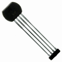
ATS625LSGTN Allegro Microsystems Inc, ATS625LSGTN Datasheet - Page 12

ATS625LSGTN
Manufacturer Part Number
ATS625LSGTN
Description
IC SENSOR GEAR TOOTH 4-SIP
Manufacturer
Allegro Microsystems Inc
Type
Special Purposer
Datasheet
1.ATS625LSGTN.pdf
(21 pages)
Specifications of ATS625LSGTN
Sensing Range
60% Trip, 40% Release
Voltage - Supply
4 V ~ 24 V
Current - Supply
14mA
Current - Output (max)
10mA
Output Type
Digital, Open Collector
Features
Gear Tooth Type
Operating Temperature
-40°C ~ 150°C
Package / Case
4-SIP
Lead Free Status / RoHS Status
Contains lead / RoHS non-compliant
Available stocks
Company
Part Number
Manufacturer
Quantity
Price
ATS625LSG
Power-On State
At power-on, the device is guaranteed to initialize in the OFF
state, with V
First Edge Detection
The device uses the first two mechanical edges to synchronize
with the target features (tooth or valley) and direction of rotation
of the target. The device is synchronized by the third edge. The
actual behavior is affected by: target rotation direction relative to
(A) Target relative movement
as shown in figure 3. Output
signal is high over the tooth.
(B) Target relative movement
opposite that shown in figure 3.
Output signal is low over the tooth.
OUT
Figure 6. Start-up Position And Relative Motion Effects on First Device Output Switching. Panel A shows the effects when the
target is moving from pin 1 toward pin 4 of the device; V
in the opposite direction, as in panel B, the polarity of the device output inverts; V
high.
Target Mechanical Profile
Target Magnetic Profile
IC Output, V
Target Mechanical Profile
Target Magnetic Profile
IC Output, V
(Start-up over falling edge)
(Start-up over falling edge)
(Start-up over rising edge)
(Start-up over rising edge)
Device Operation Description
True Zero-Speed Low-Jitter High Accuracy
(Start-up over valley)
(Start-up over valley)
(Start-up over tooth)
(Start-up over tooth)
OUT
OUT
Package
Pin 4 Side
Package
Pin 1 Side
IC start-up location
IC
OUT
start-up location
goes high at the approach of a tooth. When the target is moving
the package, target feature (tooth, rising edge, falling edge, or
valley) that is centered on the device at power-on, and fact that
the chip powers-on in the OFF state, with V
of the eventual direction of target rotation. The interaction of
these factors results in a number of possible power-on scenarios.
These are diagrammed in figure 6. In all start-up scenarios, the
correct number of output edges is provided, but the accuracy of
the first two edges may be compromised.
Target Motion Relative to Package
Target Motion Relative to Package
OUT
goes low at the approach of a tooth.
Gear Tooth Sensor IC
115 Northeast Cutoff
1.508.853.5000; www.allegromicro.com
Allegro MicroSystems, Inc.
Worcester, Massachusetts 01615-0036 U.S.A.
Package
Pin 1 Side
Package
Pin 4 Side
OUT
high, regardless
12


