A1425LK Allegro Microsystems Inc, A1425LK Datasheet - Page 3
A1425LK
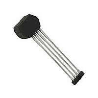
Manufacturer Part Number
A1425LK
Description
IC SENSOR HALL EFFECT AC 4-SIP
Manufacturer
Allegro Microsystems Inc
Type
Special Purposer
Datasheet
1.A1425LK-T.pdf
(13 pages)
Specifications of A1425LK
Sensing Range
11G Trip, -11G Release
Voltage - Supply
4 V ~ 26.5 V
Current - Supply
7mA
Current - Output (max)
25mA
Output Type
Digital, Open Collector
Features
High Accuracy
Operating Temperature
-40°C ~ 150°C
Package / Case
4-SIP
Magnetic Type
Monolithic
Operating Supply Voltage (min)
4V
Operating Supply Voltage (typ)
5/9/12/15/18/24V
Operating Supply Voltage (max)
26.5V
Output Current
25mA
Package Type
SIP
Pin Count
4
Mounting
Through Hole
Operating Temp Range
-40C to 150C
Operating Temperature Classification
Automotive
Lead Free Status / RoHS Status
Contains lead / RoHS non-compliant
Available stocks
Company
Part Number
Manufacturer
Quantity
Price
Company:

Part Number:
A1425LK-T
Manufacturer:
LATTICE
Quantity:
649
Part Number:
A1425LK-T
Manufacturer:
ALLEGRO/雅丽高
Quantity:
20 000


A1425
1
2
3
4
5
6
Data section.
7
8
OPERATING CHARACTERISTICS
operating range, unless otherwise noted. Typical operating parameters: V
ELECTRICAL CHARACTERISTICS
Supply Voltage
Supply Current
Output Saturation Voltage
Output Leakage Current
PROTECTION COMPONENT CHARACTERISTICS
Reverse Supply Current
Supply Zener Current
Supply Zener Clamp Voltage
Output Zener Current
Output Zener Clamp Voltage
Output Short Circuit Current Limit
RESPONSE CHARACTERISTICS
Power-On State
Power-On Time
Settling Time
Response Time
Upper Corner Frequency
Lower Corner Frequency
OUTPUT CHARACTERISTICS
Output Rise Time
Output Fall Time
MAGNETIC CHARACTERISTICS
Output Off Switchpoint
Output On Switchpoint
Applied Magnetic Field
I
Time required to initialize device.
Time required for the output switchpoints to be within specifi cation.
Output Rise Time will be dominated by the RC time constant.
For other sinusoidal signal frequencies and magnetic fi elds, –B
See Defi nitions of Terms section.
Exceeding the maximum magnetic fi eld may result in compromised absolute accuracy.
I
OUT
CC
equivalent to I
does not change state when I
Characteristic
4,7
3,7
7
CC(max)
5
6,7
6,7
+ 3 mA.
7,8
1
OUT
High Accuracy Analog Speed Sensor IC with Integrated
Filter Capacitor and Dual Zero-Crossing Output Signal
2
> I
OUTS(lim)
V
I
Symbol
t
Valid at T
V
V
OUTS(lim)
I
Response
I
OUT(SAT)
ZSupply
ZOutput
ZSupply
POS
t
ZOutput
I
V
I
B
B
Settle
B
I
RCC
t
OFF
f
CC
PO
f
cu
t
t
CC
OP
RP
cl
diff
r
f
, regardless of changes in the impinging magnetic fi eld.
A
Operating; T
I
V
V
V
I
V
I
t < t
V
f
Equal to t
–3 dB, single pole
–3 dB, single pole
R
R
B
digital output signal switches low to high
B
digital output signal switches high to low
Differential p-p magnetic fi eld
= – 40
SINK
CC
OUT
Bdiff
OUT
CC
S
OUT
CC
diff
diff
PU
PU
= 28 V
= 10 mA, T
Response
increasing, f
decreasing, f
= –18 V
> V
≥ 100 Hz
= 1 kΩ, C
= 1 kΩ, I
= 3 mA, T
= 20 mA
= 24 V, B
= 28 V
º
OP
C to 150
CC(min)
PO
= B
J
+ t
RP
SINK
< T
OUT2
A
A
diff
S
= sinα(B
Test Conditions
º
= 25°C
= 25°C
; f
C, T
Bdiff
J(max)
Bdiff
= 0
= 20 mA, C
Bdiff
= 10 pF
= 200 Hz, B
J
= 200 Hz, B
≤ 165°C; over operational air gap range and V
≥ 100 Hz
CC
diff
⁄ 2) ± 25%, where α is the phase shift shown in the Characteristic
= 12 V and T
OUT2
diff
diff
= 10 pF
= 50 Gp-p;
= 50 Gp-p;
A
= 25°C.
115 Northeast Cutoff
1.508.853.5000; www.allegromicro.com
Allegro MicroSystems, Inc.
Worcester, Massachusetts 01615-0036 U.S.A.
Min.
–11
–11
4.0
4.5
28
28
20
50
–
–
–
–
–
–
–
–
–
0
–
–
–
Typ.
High
140
4.2
4.5
33
–
–
–
–
–
–
–
–
–
–
–
–
–
0
0
–
Max.
1250
CC
26.5
400
200
200
7.0
–1
10
37
50
50
59
20
11
11
5
3
–
–
9
–
within
Units
kHz
mV
mA
mA
mA
mA
mA
ms
ms
ms
Hz
μA
ns
ns
V
V
V
V
G
G
G
3
Related parts for A1425LK
Image
Part Number
Description
Manufacturer
Datasheet
Request
R

Part Number:
Description:
IC, HALL EFFECT SENSOR, Linear, SOIC-8
Manufacturer:
Allegro Microsystems Inc
Datasheet:
Part Number:
Description:
IC, HALL EFFECT SENSOR, Linear, SOIC-8
Manufacturer:
Allegro Microsystems Inc
Datasheet:
Part Number:
Description:
IC, HALL EFFECT SENSOR, Linear, SOIC-8
Manufacturer:
Allegro Microsystems Inc
Datasheet:

Part Number:
Description:
IC SWITCH INTERFACE 2CHAN 8-SOIC
Manufacturer:
Allegro Microsystems Inc
Datasheet:

Part Number:
Description:
IC SMOKE DETECTOR ION 16-DIP
Manufacturer:
Allegro Microsystems Inc
Datasheet:
Part Number:
Description:
IC SMOKE DETECTOR ION 16-DIP
Manufacturer:
Allegro Microsystems Inc
Datasheet:
Part Number:
Description:
IC SMOKE DETECTOR ION 16-DIP
Manufacturer:
Allegro Microsystems Inc
Datasheet:
Part Number:
Description:
IC SMOKE DETECTOR PHOTO 16-DIP
Manufacturer:
Allegro Microsystems Inc
Datasheet:
Part Number:
Description:
IC SMOKE DETECTOR ION 16-DIP
Manufacturer:
Allegro Microsystems Inc
Datasheet:
Part Number:
Description:
IC SMOKE DETECTOR PHOTO 16-DIP
Manufacturer:
Allegro Microsystems Inc
Datasheet:
Part Number:
Description:
IC SMOKE DETECTOR PHOTO 16-DIP
Manufacturer:
Allegro Microsystems Inc
Datasheet:
Part Number:
Description:
IC SMOKE DETECTOR ION 16-DIP
Manufacturer:
Allegro Microsystems Inc
Datasheet:
Part Number:
Description:
IC SMOKE DETECTOR PHOTO 16-SOIC
Manufacturer:
Allegro Microsystems Inc
Datasheet:

Part Number:
Description:
IC LED DRIVER HIGH BRIGHT 16-QFN
Manufacturer:
Allegro Microsystems Inc
Datasheet:

Part Number:
Description:
IC LED DRIVER AUTOMOTIVE 8-SOIC
Manufacturer:
Allegro Microsystems Inc
Datasheet: