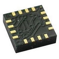
HMC5883L-TR Honeywell Microelectronics & Precision Sensors, HMC5883L-TR Datasheet - Page 8

HMC5883L-TR
Manufacturer Part Number
HMC5883L-TR
Description
IC COMPASS 3 AXIS I2C 16LCC SMD
Manufacturer
Honeywell Microelectronics & Precision Sensors
Series
HMCr
Type
Compass - Three Axisr
Specifications of HMC5883L-TR
Sensing Range
±8G
Voltage - Supply
2.16 V ~ 3.6 V
Current - Supply
100µA
Output Type
Differential Voltage
Features
Compass - Three Axis
Operating Temperature
-30°C ~ 85°C
Package / Case
16-LCC
Measuring Range
-8G To +8G
Resolution
5 MG
Supply Voltage Range
1.71V To 3.7V, 2.16V To 3.6V
No. Of Axes
3
Sensor Case Style
LCC
Ic Interface Type
I2C
Supply Voltage Max
3.6V
No. Of Pins
16
Resoluti
5 MG
Lead Free Status / RoHS Status
Lead free / RoHS Compliant
Current - Output (max)
-
Lead Free Status / RoHS Status
Lead free / RoHS Compliant
Other names
342-1082-2
Available stocks
Company
Part Number
Manufacturer
Quantity
Price
Company:
Part Number:
HMC5883L-TR
Manufacturer:
NSC
Quantity:
1 043
Part Number:
HMC5883L-TR
Manufacturer:
HONEYWELL
Quantity:
20 000
HMC5883L
BASIC DEVICE OPERATION
Anisotropic Magneto-Resistive Sensors
The Honeywell HMC5883L magnetoresistive sensor circuit is a trio of sensors and application specific support circuits to
measure magnetic fields. With power supply applied, the sensor converts any incident magnetic field in the sensitive axis
directions to a differential voltage output. The magnetoresistive sensors are made of a nickel-iron (Permalloy) thin-film and
patterned as a resistive strip element. In the presence of a magnetic field, a change in the bridge resistive elements
causes a corresponding change in voltage across the bridge outputs.
These resistive elements are aligned together to have a common sensitive axis (indicated by arrows in the pinout
diagram) that will provide positive voltage change with magnetic fields increasing in the sensitive direction. Because the
output is only proportional to the magnetic field component along its axis, additional sensor bridges are placed at
orthogonal directions to permit accurate measurement of magnetic field in any orientation.
Self Test
To check the HMC5883L for proper operation, a self test feature in incorporated in which the sensor is internally excited
with a nominal magnetic field (in either positive or negative bias configuration). This field is then measured and reported.
This function is enabled and the polarity is set by bits MS[n] in the configuration register A. An internal current source
generates DC current (about 10 mA) from the VDD supply. This DC current is applied to the offset straps of the magneto-
resistive sensor, which creates an artificial magnetic field bias on the sensor.
See SELF TEST OPERATION section later in this datasheet for additional details.
Power Management
This device has two different domains of power supply. The first one is VDD that is the power supply for internal
operations and the second one is VDDIO that is dedicated to IO interface. It is possible to work with VDDIO equal to VDD;
Single Supply mode, or with VDDIO lower than VDD allowing HMC5883L to be compatible with other devices on board.
I
Control of this device is carried out via the I
control of a master device, such as the processor.
This device is compliant with I
this device has a 7-bit serial address and supports I
and 400kHz, respectively, but does not support the high speed mode (Hs). External pull-up resistors are required to
support these standard and fast speed modes.
Activities required by the master (register read and write) have priority over internal activities, such as the measurement.
The purpose of this priority is to not keep the master waiting and the I
Internal Clock
The device has an internal clock for internal digital logic functions and timing management.
H-Bridge for Set/Reset Strap Drive
The ASIC contains large switching FETs capable of delivering a large but brief pulse to the Set / Reset strap of the
sensor. This strap is largely a resistive load. There is no need for an external Set/Reset circuit. The controlling of the
Set/Reset function is done automatically by the ASIC for each measurement. One half of the difference from the
measurements taken after a set pulse and after a reset pulse will be put in the data output register for each of the three
axes. By doing so, the sensor’s internal offset and its temperature dependence is removed/cancelled for all
measurements.
Charge Current Limit
The current that reservoir capacitor (C1) can draw when charging is limited for both single supply and dual supply
8
2
C Interface
2
C-Bus Specification, document number: 9398 393 40011. As an I
2
C bus. This device will be connected to this bus as a slave device under the
2
C protocols. This device supports standard and fast modes, 100kHz
2
C bus engaged for longer than necessary.
2
www.honeywell.com
C compatible device,


