A3423LK-T Allegro Microsystems Inc, A3423LK-T Datasheet - Page 10
A3423LK-T
Manufacturer Part Number
A3423LK-T
Description
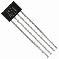
IC DIRECTION SENSOR 2CH 4-SIP
Manufacturer
Allegro Microsystems Inc
Type
Special Purposer
Specifications of A3423LK-T
Package / Case
4-SIP
Sensing Range
55G Trip, -55G Release
Voltage - Supply
3.8 V ~ 24 V
Current - Supply
14mA
Current - Output (max)
30mA
Output Type
Digital, Open Collector
Features
Regulated Voltage
Operating Temperature
-40°C ~ 150°C
Output Current
30mA
Sensor Case Style
SIP
No. Of Pins
4
Supply Voltage Range
3.8V To 24V
Operating Temperature Range
-40°C To +150°C
Base Number
3423
Supply Voltage
RoHS Compliant
Svhc
No SVHC (15-Dec-2010)
Rohs Compliant
Yes
Lead Free Status / RoHS Status
Lead free / RoHS Compliant
Other names
620-1207


A3423
5,581,179; 5,517,112; 5,619,137; 5,621,319; 5,650,719; 5,686,894; 5,694,038; 5,729,130; 5,917,320; and other patents pending.
mit improvements in the per for mance, reliability, or manufacturability of its products. Before placing an order, the user is cautioned to verify that the
information being relied upon is current.
failure of that life support device or system, or to affect the safety or effectiveness of that device or system.
nor for any in fringe ment of patents or other rights of third parties which may result from its use.
Copyright ©2007-2008, Allegro MicroSystems, Inc.
The products described herein are manufactured under one or more of the following U.S. patents: 5,045,920; 5,264,783; 5,442,283; 5,389,889;
Allegro MicroSystems, Inc. reserves the right to make, from time to time, such de par tures from the detail spec i fi ca tions as may be required to per-
Allegro’s products are not to be used in life support devices or systems, if a failure of an Allegro product can reasonably be expected to cause the
The in for ma tion in clud ed herein is believed to be ac cu rate and reliable. How ev er, Allegro MicroSystems, Inc. assumes no re spon si bil i ty for its use;
8X
C
D
E
A Terminal #1 mark area
B
Active Area Depth 0.40 NOM
Hall elements (E1 and E2); not to scale
Branding scale and appearance at supplier discretion
Reference land pattern layout (reference IPC7351
SOIC127P600X175-8M); all pads a minimum of 0.20 mm from all
adjacent pads; adjust as necessary to meet application process
requirements and PCB layout tolerances
For Reference Only; not for tooling use (reference MS-012AA)
Dimensions in millimeters
Dimensions exclusive of mold flash, gate burrs, and dambar protrusions
Exact case and lead configuration at supplier discretion within limits shown
0.10
E
C
0.51
0.31
1.09
1.27 BSC
E1
1
8
A
4.90 ±0.10
1.63
2
Dual Channel Hall Effect Direction Detection Sensor IC
E
Branded Face
For the latest version of this document, visit our website:
E2
1.95
1.63
0.25
0.10
E
E
SEATING
SEATING
PLANE
PLANE
1.75 MAX
3.90 ±0.10
Package L, 8-Pin SOIC
C
C
www.allegromicro.com
6.00 ±0.20
D
GAUGE PLANE
8°
0°
1.27
0.40
0.25 BSC
SEATING PLANE
0.25
0.17
1.04 REF
115 Northeast Cutoff
1.508.853.5000; www.allegromicro.com
Allegro MicroSystems, Inc.
Worcester, Massachusetts 01615-0036 U.S.A.
W = Week of manufacture
B
N = Device part number
Y = Last two digits of year of manufacture
L = Lot number
= Supplier emblem
C
0.65
Standard Branding Reference View
1.75
PCB Layout Reference View
1
8
1
LLLLL
NNNNNNN
2
YYWW
1.27
5.60
9
Related parts for A3423LK-T
Image
Part Number
Description
Manufacturer
Datasheet
Request
R

Part Number:
Description:
IC, HALL EFFECT SENSOR, Linear, SOIC-8
Manufacturer:
Allegro Microsystems Inc
Datasheet:
Part Number:
Description:
IC, HALL EFFECT SENSOR, Linear, SOIC-8
Manufacturer:
Allegro Microsystems Inc
Datasheet:
Part Number:
Description:
IC, HALL EFFECT SENSOR, Linear, SOIC-8
Manufacturer:
Allegro Microsystems Inc
Datasheet:

Part Number:
Description:
IC SWITCH INTERFACE 2CHAN 8-SOIC
Manufacturer:
Allegro Microsystems Inc
Datasheet:

Part Number:
Description:
IC SMOKE DETECTOR ION 16-DIP
Manufacturer:
Allegro Microsystems Inc
Datasheet:
Part Number:
Description:
IC SMOKE DETECTOR ION 16-DIP
Manufacturer:
Allegro Microsystems Inc
Datasheet:
Part Number:
Description:
IC SMOKE DETECTOR ION 16-DIP
Manufacturer:
Allegro Microsystems Inc
Datasheet:
Part Number:
Description:
IC SMOKE DETECTOR PHOTO 16-DIP
Manufacturer:
Allegro Microsystems Inc
Datasheet:
Part Number:
Description:
IC SMOKE DETECTOR ION 16-DIP
Manufacturer:
Allegro Microsystems Inc
Datasheet:
Part Number:
Description:
IC SMOKE DETECTOR PHOTO 16-DIP
Manufacturer:
Allegro Microsystems Inc
Datasheet:
Part Number:
Description:
IC SMOKE DETECTOR PHOTO 16-DIP
Manufacturer:
Allegro Microsystems Inc
Datasheet:
Part Number:
Description:
IC SMOKE DETECTOR ION 16-DIP
Manufacturer:
Allegro Microsystems Inc
Datasheet:
Part Number:
Description:
IC SMOKE DETECTOR PHOTO 16-SOIC
Manufacturer:
Allegro Microsystems Inc
Datasheet:

Part Number:
Description:
IC LED DRIVER HIGH BRIGHT 16-QFN
Manufacturer:
Allegro Microsystems Inc
Datasheet:

Part Number:
Description:
IC LED DRIVER AUTOMOTIVE 8-SOIC
Manufacturer:
Allegro Microsystems Inc
Datasheet: