A3290KUA-T Allegro Microsystems Inc, A3290KUA-T Datasheet - Page 5
A3290KUA-T
Manufacturer Part Number
A3290KUA-T
Description
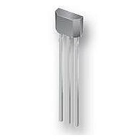
IC HALL EFFECT LATCH 3-SIP
Manufacturer
Allegro Microsystems Inc
Type
Bipolar Latchr
Specifications of A3290KUA-T
Package / Case
3-SIP
Sensing Range
50G Trip, -50G Release
Voltage - Supply
4.2 V ~ 24 V
Current - Supply
8mA
Current - Output (max)
25mA
Output Type
Digital, Open Drain
Features
Regulated Voltage
Operating Temperature
-40°C ~ 125°C
Hall Effect Type
Latch
Output Current
25mA
Sensor Case Style
SIP
No. Of Pins
3
Supply Voltage Range
4.2V To 24V
Operating Temperature Range
-40°C To +125°C
Bandwidth
800kHz
Svhc
No SVHC (15-Dec-2010)
Rohs Compliant
Yes
Lead Free Status / RoHS Status
Lead free / RoHS Compliant


A3290
A3291
Chopper-Stabilized Technique
The Hall element can be considered as a resistor array similar
to a Wheatstone bridge. A basic circuit is shown in figure 1,
demonstrating the effect of the magnetic field flux density, B,
impinging on the Hall element. When using Hall effect tech-
nology, a limiting factor for switchpoint accuracy is the small
signal voltage, V
voltage is disproportionally small relative to the offset that can
be produced at the output of the Hall device, caused by device
overmolding, temperature dependencies, and thermal stress.
A large portion of the offset is a result of the mismatching of
these resistors. The A3290 and A3291 use a proprietary dynamic
offset cancellation technique, with an internal high-frequency
clock, to reduce the ressidual offset. The chopper-stabilizing
Figure 1. Hall element, basic circuit operation
Figure 2. Chopper stabilization circuit (dynamic quadrature offset
cancellation)
Regulator
and
HALL
+V
, developed across the Hall element. This
CC
B
Chopper Stabilized, Precision Hall Effect Latches
Amp
+V
–V
HALL
HALL
for Consumer and Industrial Applications
Functional Description
Low-
Pass
Filter
technique cancels the mismatching of the resistor circuit by
changing the direction of the current flowing through the Hall
element. To do so, CMOS switches and Hall voltage measure-
ment taps are used, while maintaining V
induced by the external magnetic flux.
The signal is then captured by a sample-and-hold circuit and fur-
ther processed using low-offset bipolar circuitry. This technique
produces devices that have an extremely stable quiescent Hall
output voltage, are immune to thermal stress, and have precise
recoverability after temperature cycling. This technique will also
slightly degrade the device output repeatability. A relatively high
sampling frequency is used in order to process faster signals.
More detailed descriptions of the circuit operation can be found
on the Allegro Web site, including: Technical Paper STP 97-10,
Monolithic Magnetic Hall Sensor Using Dynamic Quadrature
Offset Cancellation, and Technical Paper STP 99-1, Chopper-
Stabilized Amplifiers with a Track-and-Hold Signal Demodula-
tor.
Operation
The outputs of the A3290 and A3291 switch low (turn on) when
a magnetic field perpendicular to the Hall sensor transitions
through and exceeds the Operate Point threshold, B
illustrated in figure 3. After turn-on, the output is capable of
sinking 25 mA, and the output voltage reaches V
Figure 3. Output voltage responds to sensed magnetic flux density.
V+
Switching Due to ΔB
Hysteresis of ΔV
B
115 Northeast Cutoff
1.508.853.5000; www.allegromicro.com
Allegro MicroSystems, Inc.
Worcester, Massachusetts 01615-0036 U.S.A.
HYS
OUT
B+
HALL
V
V
OUT(off)
OUT(on)(sat)
signal that is
OUT(SAT)
OP
. This is
.
5
Related parts for A3290KUA-T
Image
Part Number
Description
Manufacturer
Datasheet
Request
R

Part Number:
Description:
SOCKET ADPTR PLCC/84PIN .600 DIP
Manufacturer:
Aries Electronics
Datasheet:

Part Number:
Description:
IC, HALL EFFECT SENSOR, Linear, SOIC-8
Manufacturer:
Allegro Microsystems Inc
Datasheet:
Part Number:
Description:
IC, HALL EFFECT SENSOR, Linear, SOIC-8
Manufacturer:
Allegro Microsystems Inc
Datasheet:
Part Number:
Description:
IC, HALL EFFECT SENSOR, Linear, SOIC-8
Manufacturer:
Allegro Microsystems Inc
Datasheet:

Part Number:
Description:
IC SWITCH INTERFACE 2CHAN 8-SOIC
Manufacturer:
Allegro Microsystems Inc
Datasheet:

Part Number:
Description:
IC SMOKE DETECTOR ION 16-DIP
Manufacturer:
Allegro Microsystems Inc
Datasheet:
Part Number:
Description:
IC SMOKE DETECTOR ION 16-DIP
Manufacturer:
Allegro Microsystems Inc
Datasheet:
Part Number:
Description:
IC SMOKE DETECTOR ION 16-DIP
Manufacturer:
Allegro Microsystems Inc
Datasheet:
Part Number:
Description:
IC SMOKE DETECTOR PHOTO 16-DIP
Manufacturer:
Allegro Microsystems Inc
Datasheet:
Part Number:
Description:
IC SMOKE DETECTOR ION 16-DIP
Manufacturer:
Allegro Microsystems Inc
Datasheet:
Part Number:
Description:
IC SMOKE DETECTOR PHOTO 16-DIP
Manufacturer:
Allegro Microsystems Inc
Datasheet:
Part Number:
Description:
IC SMOKE DETECTOR PHOTO 16-DIP
Manufacturer:
Allegro Microsystems Inc
Datasheet:
Part Number:
Description:
IC SMOKE DETECTOR ION 16-DIP
Manufacturer:
Allegro Microsystems Inc
Datasheet:
Part Number:
Description:
IC SMOKE DETECTOR PHOTO 16-SOIC
Manufacturer:
Allegro Microsystems Inc
Datasheet:

Part Number:
Description:
IC LED DRIVER HIGH BRIGHT 16-QFN
Manufacturer:
Allegro Microsystems Inc
Datasheet: