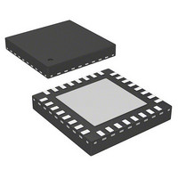
AS5245-HQFT-500 austriamicrosystems, AS5245-HQFT-500 Datasheet - Page 17

AS5245-HQFT-500
Manufacturer Part Number
AS5245-HQFT-500
Description
IC ENCODER ROTARY 32-QFN
Manufacturer
austriamicrosystems
Type
Linear, Rotary Encoder - Programmabler
Datasheet
1.AS5245-HQFT-500.pdf
(31 pages)
Specifications of AS5245-HQFT-500
Featured Product
AS5245 â Dual Die Motion Sensing IC
Sensing Range
45mT ~ 75mT
Voltage - Supply
3 V ~ 3.6 V, 4.5 V ~ 5.5 V
Current - Supply
21mA
Current - Output (max)
4mA
Output Type
Quadrature with Index (Incremental)
Features
Programmable
Operating Temperature
-40°C ~ 150°C
Package / Case
32-VQFN Exposed Pad
Lead Free Status / RoHS Status
Lead free / RoHS Compliant
Other names
AS5245-HQFT-500TR
AS5245
Data Sheet - A p p l i c a t i o n I n f o r m a t i o n
9 Application Information
The benefits of AS5245 are as follows:
9.1 Programming the AS5245
After power-on, programming the AS5245 is enabled with the rising edge of CSn with PDIO = high and CLK = low.
The AS5245 programming is a one-time programming (OTP) method, based on poly silicon fuses. The advantage of this method is that a
programming voltage of only 3.3V to 3.6V is required for programming.
The OTP consists of 52 bits, of which 21 bits are available for user programming. The remaining 31 bits contain factory settings and a unique
chip identifier (Chip-ID).
A single OTP cell can be programmed only once. Per default, the cell is “0”; a programmed cell will contain a “1”. While it is not possible to reset
a programmed bit from “1” to “0”, multiple OTP writes are possible, as long as only unprogrammed “0”-bits are programmed to “1”.
Independent of the OTP programming, it is possible to overwrite the OTP register temporarily with an OTP write command at any time. This
setting will be cleared and overwritten with the hard programmed OTP settings at each power-up sequence or by a LOAD operation. Use
application note AN514X_10 to get more information about the programming options.
The OTP memory can be accessed in the following ways:
9.1.1 Zero Position Programming
Zero position programming is an OTP option that simplifies assembly of a system, as the magnet does not need to be manually adjusted to the
mechanical zero position. Once the assembly is completed, the mechanical and electrical zero positions can be matched by software. Any
position within a full turn can be defined as the permanent new zero position.
For zero position programming, the magnet is turned to the mechanical zero position (e.g. the “off”-position of a rotary switch) and the actual
angular value is read.
This value is written into the OTP register bits Z35:Z46.
Note: The zero position value may also be modified before programming, e.g. to program an electrical zero position that is 180º (half turn)
www.austriamicrosystems.com/AS5245
Complete system-on-chip
Angle measurement with programmable range up to 360º
High reliability due to non-contact magnetic sensing
Ideal for applications in harsh environments
Robust system, tolerant to magnet misalignment, airgap variations, temperature variations and external magnetic fields
No calibration required
Building of redundancy systems with plausibility checks
Load Operation: The Load operation reads the OTP fuses and loads the contents into the OTP register. A Load operation is automatically
executed after each power-on-reset.
Write Operation: The Write operation allows a temporary modification of the OTP register. It does not program the OTP. This operation can
be invoked multiple times and will remain set while the chip is supplied with power and while the OTP register is not modified with another
Write or Load operation.
Read Operation: The Read operation reads the contents of the OTP register, for example to verify a Write command or to read the OTP
memory after a Load command.
Program Operation: The Program operation writes the contents of the OTP register permanently into the OTP ROM.
Analog Readback Operation: The Analog Readback operation allows a quantifiable verification of the programming. For each
programmed or unprogrammed bit, there is a representative analog value (in essence, a resistor value) that is read to verify whether a bit
has been successfully programmed or not.
from the mechanical zero position, just add 2048 to the value read at the mechanical zero position and program the new value into the
OTP register.
Revision 1.5
17 - 31


