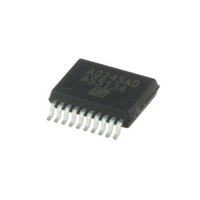
AS5134-ZSST austriamicrosystems, AS5134-ZSST Datasheet - Page 2

AS5134-ZSST
Manufacturer Part Number
AS5134-ZSST
Description
IC ENCODER PROG 20-SSOP
Manufacturer
austriamicrosystems
Type
Linear, Rotary Encoder - Programmabler
Datasheet
1.AS5134_PB.pdf
(40 pages)
Specifications of AS5134-ZSST
Sensing Range
20mT ~ 80mT
Voltage - Supply
4.5 V ~ 5.5 V
Current - Supply
15mA
Output Type
Digital, PWM
Features
Programmable
Operating Temperature
-40°C ~ 140°C
Package / Case
20-SSOP
Lead Free Status / RoHS Status
Lead free / RoHS Compliant
Current - Output (max)
-
Other names
AS5134-ZSSTTR
Available stocks
Company
Part Number
Manufacturer
Quantity
Price
Company:
Part Number:
AS5134-ZSST
Manufacturer:
ICT
Quantity:
1 200
AS5134
Data Sheet - C o n t e n t s
Contents
1 General Description ..................................................................................................................................................................
2 Key Features.............................................................................................................................................................................
3 Applications...............................................................................................................................................................................
4 Pin Assignments .......................................................................................................................................................................
5 Absolute Maximum Ratings ......................................................................................................................................................
6 Electrical Characteristics...........................................................................................................................................................
7 Detailed Description..................................................................................................................................................................
8 Application Information ...........................................................................................................................................................
www.austriamicrosystems.com/AS5134
4.1 Pin Descriptions.................................................................................................................................................................................... 4
6.1 Timing Characteristics .......................................................................................................................................................................... 8
7.1 Connecting the AS5134........................................................................................................................................................................ 9
7.2 Serial 3-Wire R/W Connection............................................................................................................................................................ 10
7.3 Serial 3-Wire Read-only Connection ..................................................................................................................................................
7.4 Serial 2-Wire Connection (R/W Mode) ............................................................................................................................................... 12
7.5 Serial 2-Wire Differential SSI Connection........................................................................................................................................... 13
7.6 1-Wire PWM Connection .................................................................................................................................................................... 14
7.7 Analog Output..................................................................................................................................................................................... 15
7.8 Quadrature A/B/Index Output ............................................................................................................................................................. 15
7.9 Brushless DC Motor Commutation Mode ........................................................................................................................................... 16
7.10 Daisy Chain Mode ............................................................................................................................................................................ 16
7.11 Serial Synchronous Interface (SSI) .................................................................................................................................................. 18
7.12 Redundancy ..................................................................................................................................................................................... 20
8.1 AS5134 Programming ........................................................................................................................................................................ 22
8.2 AS5134 Status Indicators ................................................................................................................................................................... 24
8.3 Multi Turn Counter.............................................................................................................................................................................. 25
8.4 High Speed Operation ........................................................................................................................................................................ 26
8.5 Magnet Diameter and Vertical Distance ............................................................................................................................................. 28
8.6 AS5134 Parameter and Features List ................................................................................................................................................ 34
8.1.1 OTP Programming Connection.................................................................................................................................................. 22
8.1.2 Programming Verification .......................................................................................................................................................... 23
8.2.1 Lock Status Bit........................................................................................................................................................................... 24
8.2.2 Magnetic Field Strength Indicators ............................................................................................................................................ 25
8.4.1 Propagation Delay ..................................................................................................................................................................... 26
8.4.2 ADC Sampling Rate................................................................................................................................................................... 26
8.4.3 Chip Internal Lowpass Filtering ................................................................................................................................................. 26
8.4.4 Digital Readout Rate.................................................................................................................................................................. 26
8.4.5 Total Propagation Delay of the AS5134 .................................................................................................................................... 26
8.4.6 Low Power Mode ....................................................................................................................................................................... 27
8.5.1 The Linear Range ...................................................................................................................................................................... 28
8.5.2 Magnet Thickness...................................................................................................................................................................... 30
8.5.3 Axial Distance (Airgap) .............................................................................................................................................................. 30
8.5.4 Angle Error vs. Radial and Axial Misalignment.......................................................................................................................... 31
8.5.5 Accuracy .................................................................................................................................................................................... 31
8.5.6 Mounting the Magnet ................................................................................................................................................................. 32
8.5.7 Summary ................................................................................................................................................................................... 34
Revision 1.13
2 - 40
22
11
1
1
1
4
5
6
9


