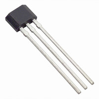
US1881EUA Melexis Inc, US1881EUA Datasheet - Page 32

US1881EUA
Manufacturer Part Number
US1881EUA
Description
IC LATCH CMOS MP TO-92UA
Manufacturer
Melexis Inc
Type
Bipolar Latchr
Specifications of US1881EUA
Sensing Range
9.5mT Trip, -9.5mT Release
Voltage - Supply
3.5 V ~ 24 V
Current - Supply
5mA
Current - Output (max)
50mA
Output Type
Digital, Open Drain
Operating Temperature
-40°C ~ 85°C
Package / Case
TO-92UA
Lead Free Status / RoHS Status
Lead free / RoHS Compliant
Features
-
Programmable Isolated Current Sensor
Hall Effect Sensors can be used in conjunction with an electromagnet to make a very efficient, isolated
current-sensing device. This can be used to protect components from damage such as overheating.
The only components needed, as in Figure 13, are a Hall IC and a slotted ferrite toroid core driving an
indicator, relay or a logic-level fault signal. The ideal Hall IC in this application is a programmable linear
device, which would allow accurate calibration of the sensor and also versatility. For example, the dia-
gram below shows a toroid with 4 turns of wire. If a current of 10A was applied to the coil, the field at
the sensor would be about 6mT. The Hall IC can be programmed to give the desired response to this mag-
netic range. If the desired voltage swing is 0.5V (or 500mV) and the magnetic swing is 6mT, then the
device can be programmed to
Figure 18, Programmable Current Sensor
83mV/mT to give the correct
response.
By varying the number of
windings and the programming
codes, rages as small as 100mA
and as large as 500A can be
achieved.
If used with a linear Hall-Effect
sensor, the output voltage will
be proportional to the current
flowing through the windings
on the toroid. This Voltage can
be used to indicate current
level, or trigger a shut-down
circuit.
PTC
TM
Current Indicator/Limiter
If only a current indicator or limiter is needed, a simple circuit can be built with a Hall switch, and requires
no programming. In Figure 13, each complete turn of coil around the core, with a current of 1 Amp flow -
ing through it, will produce a flux density of approximately .6 mT upon the Hall Effect Switch. By adjust-
ing the number of coil turns around the core, the Hall Effect switch can act as either a current indicator or
current limiter.
Example:
Under normal operation a current of 10 Amps is delivered to a motor by some wire. Wrapping four turns
of the wire around the core will produce a magnetic field of 24 mT upon the Hall IC, which will activate
the device to ON. This can be used to illuminate an LED to symbolizing “normal” current. The LED will
remain ON until the field drops to about 18mT or about 7.5 Amps.
To use as a limiter, simply drop one turn of wire, which will require a higher current to turn the Hall switch
ON. With 1 turn removed, the switch will require 13 Amps to turn ON, and will remain on until the cur-
rent level drops below 1Amp.
Section 3 - Applications
3-18


