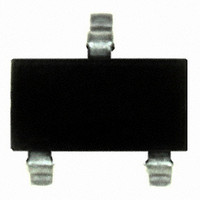
US4881ESE Melexis Inc, US4881ESE Datasheet - Page 8

US4881ESE
Manufacturer Part Number
US4881ESE
Description
IC HALL SW BIPO NORTH POLE SOT23
Manufacturer
Melexis Inc
Type
Bipolar Latchr
Specifications of US4881ESE
Sensing Range
6mT Trip, -6mT Release
Voltage - Supply
2.2 V ~ 18 V
Current - Supply
5mA
Current - Output (max)
50mA
Output Type
Digital, Open Drain
Operating Temperature
-40°C ~ 85°C
Package / Case
SOT-23
Lead Free Status / RoHS Status
Lead free / RoHS Compliant
Features
-
Other names
US4881ESETR
13 Application Information
13.1 Typical Three-Wire Application Circuit
13.3 Automotive and Harsh, Noisy Environments
13.4 Application Comments
For proper operation, a 100nF bypass capacitor should be placed as close as possible to the device between
the V
For reverse voltage protection, it is recommended to connect a resistor or a diode in series with the V
When using a resistor, three points are important:
When using a diode, a reverse current cannot flow and the voltage drop is almost constant (≈0.7V).
Therefore, a 100Ω/0.25W resistor for 5V application and a diode for higher supply voltage are recommended.
Both solutions provide the required reverse voltage protection.
When a weak power supply is used or when the device is intended to be used in noisy environment, it is
recommended that figure 13.3 from the Application Information section is used.
The low-pass filter formed by R1 and C1 and the zener diode Z1 bypass the disturbances or voltage spikes
occurring on the device supply voltage V
3901004881
Rev 012
DD
Three-Wire Circuit
and ground pin.
- the resistor has to limit the reverse current to 50mA maximum (V
- the resulting device supply voltage V
- the resistor has to withstand the power dissipated in reverse voltage condition (P
DD
. The diode D1 provides additional reverse voltage protection.
DD
Page 8 of 12
has to be higher than V
Low Voltage & Very High Sensitivity
13.2 Two-Wire Circuit
Note:
With this circuit, precise ON and OFF
currents can be detected using only
two connecting wires.
The resistors RL and Rb can be used
to bias the input current. Refer to the
part specifications for limiting values.
B
B
DD
RP
OP
CC
min (V
:
:
/ R1 ≤ 50mA)
I
I
OFF
ON
Bipolar Hall Switch
DD
= I
= I
= V
OFF
R
+ I
CC
+ I
US4881
D
DD
– R1·I
OUT
= V
= V
= I
CC
Data Sheet
Jan/07
DD
DD
OFF
2
/R
)
/ R1)
+ V
b
DD
+ I
pin.
DD
DD
/R
L


