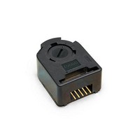
HEDS-5540#C12 Avago Technologies US Inc., HEDS-5540#C12 Datasheet - Page 8

HEDS-5540#C12
Manufacturer Part Number
HEDS-5540#C12
Description
ENCODER OPTICAL 100 CPR 6MM SHFT
Manufacturer
Avago Technologies US Inc.
Series
HEDSr
Type
Optical Encoderr
Datasheet
1.HEDS-8907-001.pdf
(12 pages)
Specifications of HEDS-5540#C12
Pulses Per Revolution
100
Built In Switch
No
Encoder Type
Optical
Output Type
Quadrature with Index (Incremental)
Voltage - Supply
5VDC
Actuator Type
6mm Open Center
Detent
No
Mounting Type
Chassis Mount, Motors
Orientation
Vertical
Termination Style
Terminal Pins
Detents
No
Motion
Rotary
Number Of Channels
3
Mounting Style
Through Hole
Index Output
Indexed
Encoder Signal
Digital
Shaft Style
Round
Shaft Diameter (mm)
6mm
Operating Supply Voltage (typ)
5VDC
Operating Temperature Min Deg. C
-40C
Operating Temperature Max Deg. C
100C
Terminal Type
PC Pins
Output
Quadrature with Index
Supply Voltage
5 V
Operating Temperature Range
- 40 C to + 100 C
Product
Kits
Rotational Life (cycles Min)
-
Lead Free Status / Rohs Status
Lead free / RoHS Compliant
Other names
HEDS-5540C12
Q2421664
Q2421664
Available stocks
Company
Part Number
Manufacturer
Quantity
Price
Mounting Considerations
The HEDS-5540 and 5640 three channel encoders and the
HEDM Series high resolution encoders must be aligned
using the aligning pins as specified in Figure 3, or using
the HEDS-8910 Alignment Tool as shown in Encoder
Mounting and Assembly.
The use of aligning pins or alignment tool is recommend-
ed but not required to mount the HEDS-5500 and 5600.
If these two channel encoders are attached to a motor
with the screw sizes and mounting tolerances specified
in the mechanical characteristics section without any
Figure 2. Mounting Holes.
Figure 4. Mounting with External Ears.
8
Figure 3. Optional Mounting Aids.
additional mounting bosses, the encoder output errors
will be within the maximums specified in the encoding
characteristics section. The HEDS-5500 and 5540 can be
mounted to a motor using either the two screw or three
screw mounting option as shown in Figure 2. The optional
aligning pins shown in Figure 3 can be used with either
mounting option. The HEDS-5600, 5640, and HEDM-5600
have external mounting ears which may be used for
mounting to larger motor base plates. Figure 4 shows the
necessary mounting holes with optional aligning pins and
motor boss.


