AEDB-9140-A05 Avago Technologies US Inc., AEDB-9140-A05 Datasheet - Page 4
AEDB-9140-A05
Manufacturer Part Number
AEDB-9140-A05
Description
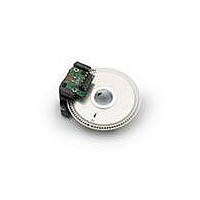
MOD ENCODER 3CH 500CPR 28MM 3/16
Manufacturer
Avago Technologies US Inc.
Series
AEDB-9140r
Type
Optical Encoderr
Datasheet
1.AEDB-9140-A04.pdf
(9 pages)
Specifications of AEDB-9140-A05
Pulses Per Revolution
500
Encoder Type
Optical
Output Type
Quadrature with Index (Incremental)
Voltage - Supply
5VDC
Actuator Type
3/16" Open Center
Detent
No
Built In Switch
No
Mounting Type
Chassis Mount, Motors
Termination Style
Terminal Pins
Number Of Channels
3
Supply Voltage
5 V
Product
Optical
Detents
No
Motion
Rotary
Mounting Style
Screw
Index Output
Indexed
Encoder Signal
Digital
Shaft Style
Hollow
Shaft Diameter (mm)
4.76mm
Operating Supply Voltage (typ)
5VDC
Operating Temperature Min Deg. C
-10C
Operating Temperature Max Deg. C
85C
Lead Free Status / RoHS Status
Lead free / RoHS Compliant
Orientation
-
Rotational Life (cycles Min)
-
Lead Free Status / Rohs Status
Compliant


Defi nitions
Note: Refer to Figure 2
Count (N): The number of bar and window pairs or counts
per revolution (CPR) of the codewheel.
One Cycle (C): 360 electrical degrees (°e), 1 bar and win-
dow pair.
One Shaft Rotation: 360 mechanical degrees, N cycles.
Position Error (ΔΘ): The normalized angular diff erence
between the actual shaft position and the position indi-
cated by the encoder cycle count.
Cycle Error (ΔC): An indication of cycle uniformity. The
diff erence between an observed shaft angle which gives
rise to one electrical cycle, and the nominal angular incre-
ment of 1/N of a revolution.
Pulse Width (P): The number of electrical degrees that
an output is high during 1 cycle. This value is nominally
180°e or 1/2 cycle.
Pulse Width Error (ΔP): The deviation, in electrical degrees,
of the pulse width from its ideal value of 180°e.
State Width (S): The number of electrical degrees be-
tween a transition in the output of channel A and the
neighboring transition in the output of channel B. There
are 4 states per cycle, each nominally 90°e.
4
State Width Error (ΔS): The deviation, in electrical degrees,
of each state width from its ideal value of 90°e.
Phase (f ): The number of electrical degrees between the
center of the high state of channel A and the center of
the high state of channel B.
This value is nominally 90°e for quadrature output.
Phase Error (Δφ): The deviation of the phase from its ideal
value of 90°e.
Direction of Rotation: When the codewheel rotates in
the clockwise direction viewing from top of the module
(direction from V to G), channel A will lead channel B. If
the codewheel rotates in the opposite direction, channel
B will lead channel A.
Optical Radius (Rop): The distance from the codewheel’s
center of rotation to the optical center (O.C) of the en-
coder module.
Index Pulse Width (Po): The number of electrical degrees
that an index is high during one full shaft rotation. This
value is nominally 90°e or 1/4 cycle.
Related parts for AEDB-9140-A05
Image
Part Number
Description
Manufacturer
Datasheet
Request
R

Part Number:
Description:
MOD ENCODER 3CH 500CPR 28MM 5/32
Manufacturer:
Avago Technologies US Inc.
Datasheet:
Part Number:
Description:
MOD ENCODER 3CH 100CPR 28MM 1/4"
Manufacturer:
Avago Technologies US Inc.
Datasheet:
Part Number:
Description:
MOD ENCODER 3CH 100CPR 28MM 6MM
Manufacturer:
Avago Technologies US Inc.
Datasheet:
Part Number:
Description:
MOD ENCODER 3CH 100CPR 28MM 8MM
Manufacturer:
Avago Technologies US Inc.
Datasheet:
Part Number:
Description:
MOD ENCODER 3CH 200CPR 28MM 1/4"
Manufacturer:
Avago Technologies US Inc.
Datasheet:
Part Number:
Description:
MOD ENCODER 3CH 200CPR 28MM 4MM
Manufacturer:
Avago Technologies US Inc.
Datasheet:
Part Number:
Description:
MOD ENCODER 3CH 256CPR 28MM 5/32
Manufacturer:
Avago Technologies US Inc.
Datasheet:

Part Number:
Description:
En,6Ch,1000CPR,G CW,29mm,2pp, 8mm
Manufacturer:
Avago Technologies US Inc.
Datasheet:
Part Number:
Description:
En,6Ch,1000CPR,G CW,29mm,4pp,8mm
Manufacturer:
Avago Technologies US Inc.
Datasheet:
Part Number:
Description:
En,6Ch,1024CPR,G CW,29.4mm,2pp,8mm
Manufacturer:
Avago Technologies US Inc.
Datasheet:

Part Number:
Description:
OPTOCOUPLER GATE DRV 2A 16-SOIC
Manufacturer:
Avago Technologies US Inc.
Datasheet:
Part Number:
Description:
OPTOCOUPLER 2CH 2.5A 16-SOIC
Manufacturer:
Avago Technologies US Inc.
Datasheet:

Part Number:
Description:
OPTOCOUPLER GATE DRV 0.4A 16SOIC
Manufacturer:
Avago Technologies US Inc.
Datasheet:

Part Number:
Description:
OPTOCOUPLER 2.0A 250KHZ 8-DIP
Manufacturer:
Avago Technologies US Inc.
Datasheet:

Part Number:
Description:
OPTOCOUPLER 2.0A 250KHZ GW 8-SMD
Manufacturer:
Avago Technologies US Inc.
Datasheet: