19-905 EAO, 19-905 Datasheet
19-905
Specifications of 19-905


Related parts for 19-905


19-905 Summary of contents
Page 1
... EAO – Your Expert Partner for Human Machine Interfaces EAO Product Information Series 19 ...
Page 2
...
Page 3
... Switches and Indicators 19 ...
Page 4
... Contents Description ...................................................................................................... 3 Product Assembly .......................................................................................... 4 Devices raised mounting ............................................................................... 5 Accessories..................................................................................................... 6 Technical Data................................................................................................. 9 Application guidelines.................................................................................. 11 Drawings........................................................................................................ 12 Index............................................................................................................... 15 2 04.2009 19 ...
Page 5
... The status of a maintained action switch can be determinded by the position of the lens. Specimen order 0 Indicator : - Indicator actuator dia., soldering terminal Essential accessories : - Lens plastic blue, transparent, flush dia. - Single-LED, T1 Bi-Pin, 3.6 VDC, weiss We reserve the right to modify technical data All dimensions 19-030.005 19-931.6 10-2603.3179C 3 04.2009 ...
Page 6
... Product Assembly Indicator, raised mounting Pushbutton illuminative, raised mounting 04.2009 1 Lens 2 Switch housing 3 Front plate 4 Fixing nut 1 Lens 2 Switch housing 3 Front plate 4 Fixing nut 19 ...
Page 7
... Terminals Soldering terminal (also pluggable 2.0 x 0.5 mm) Component layout from page 12, Mounting dimensions from page 12, Technical drawing from page 13, Circuit drawing from page Typ-Nr 19-050.005 19-051.005 Typ-Nr 19-482.035 M S2 19-452.035 19-481.035 M S2 19-451.035 19-289.035 M S2 19-159.035 19-289.015 M S2 19-159.015 19 Ø Typ-Nr. 19-030.005 0.001 19-031.005 1 ...
Page 8
... Plastic flush opaque grey 19-951 Typ-Nr. 19-948 Ø Typ-Nr. 19-931.6 0.001 19-931.5 0.001 19-931.2 0.001 19-931.9 0.001 19-931.4 0.001 19-932.6 0.001 19-932.7 0.001 19-932.5 0.001 19-932.2 0.001 19-932.4 0.001 19-931.0 0.001 19-931.8 0.001 Ø Typ-Nr. 19-949.0 1 0.001 e Typ-Nr. 19-940 3 4 0.001 ...
Page 9
... VDC Light colour Operating voltage/-current green 28 VDC orange 28 VDC red 28 VDC yellow 28 VDC Typ-Nr. 31-945 0.001 e Typ-Nr. 31-928 0.001 e Typ-Nr. 10-1609.1199 0.001 10-1612.1179 0.001 10-1606.1309 0.001 e Typ-Nr. 10-2602.3175C 0.001 10-2602.3172C 0.001 10-2603.3179C 0.001 10-2602.3174C 0.001 e Typ-Nr. 10-4613.3105B 0.001 10-4613.3103B 0.001 10-4613 ...
Page 10
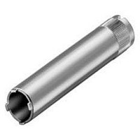
... Lamp remover CAUTION A switching process might be released when replacing the Lamp/LED ! Mounting tool Continuation see next page Mounting tool for Fixing nut long 19-991 8 04.2009 19 e Typ-Nr. 19-991 0.001 e Typ-Nr. 19-906 0.011 e Typ-Nr. 19-910 0.002 e Typ-Nr. 11-906 0.003 e Typ-Nr. 19-905 0.011 ...
Page 11
... VAC/VDC Electric strength 2500 VAC, 50 Hz, 1 min. between all terminals and earth, as per IEC 60512-2-11 Environmental conditions Storage temperature -40 °C ... +85 °C Service temperature without illumination -25 °C ... +65 °C with incandescent lamp -25 °C ... +45 °C with LED -25 °C ... +65 ° 04.2009 ...
Page 12
... Technical Data for indicators and illuminated pushbuttons mounted as a block, make sure the heat can escape freely Protection degree IP 40 front side, as per IEC 60529 Shock resistance (Single impacts, semi-sinusoidal for 11 ms, as per IEC 60512-4-3, IEC 60068-2-27 10 04.2009 19 ...
Page 13
... To get an efficient protection, the free-wheeling diode must be connected as close as possible to the inductive load! 0 Switching with inductive load Fig. 1 Switch + Free-wheeling Inductive VDC _ diode load Counter emf over load without free-wheeling diode Fig OFF 0 Sveral hundred to several thousend volts 04.2009 ...
Page 14
... PCB plug-in base page 6 Drilling plan (element side) Through-connection recommended 2x Ø1.1 10.16 2.54 Pins for mounting 2.3 4x Ø1.1 Pins for 11.7 contact / LED Mounting dimensions 1 Indicator actuator page 5 | Illuminated pushbutton actuator page 5 | Blind plug page Ø +0.2 +0 min. 12 04.2009 9 min. 19 ...
Page 15
... Drawings Technical drawing 1 Indicator actuator page Ø max. 5 Illuminated pushbutton actuator page 5 8 max Ø Indicator actuator page Ø max. 5 PCB plug-in base page 6 11.7 3.2 8.9 5 PCB plug-in base page 6 11.7 3.35 8 04.2009 ...
Page 16
... Drawings Circuit drawing 1 Indicator actuator page Illuminated pushbutton actuator page Illuminated pushbutton actuator page Illuminated pushbutton actuator page Illuminated pushbutton actuator page 04.2009 19 ...
Page 17
... 19-030.005 ................................... 5 19-031.005 ................................... 5 19-050.005 ................................... 5 19-051.005 ................................... 5 19-139.015 ................................... 5 19-139.035 ................................... 5 19-159.015 ................................... 5 19-159.035 ................................... 5 19-279.015 ................................... 5 19-279.035 ................................... 5 19-289.015 ................................... 5 19-289.035 ................................... 5 19-431.035 ................................... 5 19-432.035 ................................... 5 19-451.035 ................................... 5 19-452.035 ................................... 5 19-471.035 ................................... 5 19-472.035 ................................... 5 19-481.035 ................................... 5 19-482.035 ................................... 5 19-905 .......................................... 8 19-906 .......................................... 8 19-910 .......................................... 8 19-931.0 ....................................... 6 19-931.2 ....................................... 6 19-931.4 ....................................... 6 19-931.5 ....................................... 6 19-931.6 ....................................... 6 19-931.8 ....................................... 6 19-931.9 ....................................... 6 19-932.2 ....................................... 6 19-932.4 ....................................... 6 19-932.5 ....................................... 6 19-932.6 ....................................... 6 19-932.7 ....................................... 6 19-940 .......................................... 6 19-941 .......................................... 6 19-948.0 ....................................... 6 19-949.0 ....................................... 6 19-951.0 ....................................... 6 19-951.2 ....................................... 6 19-951 ...
Page 18
... Tannwaldstrasse 88 4601 Olten, Switzerland E-mail info@eao.com Website www.eao.com Austria Phone +49 201 Fax +49 201 85 87 210 E-mail sales.ede@eao.com Belgium Phone +32 3 777 82 36 Fax +32 3 777 84 19 E-mail sales.ebl@eao.com China Phone +852 Fax +852 E-mail sales.ehk@eao.com France Phone + Fax + E-mail sales.ese@eao.com Germany ...