71-672.026 EAO, 71-672.026 Datasheet
71-672.026
Specifications of 71-672.026


Related parts for 71-672.026


71-672.026 Summary of contents
Page 1
... EAO – Your Expert Partner for Human Machine Interfaces EAO Product Information Series 71 ...
Page 2
...
Page 3
... Switches and Indicators 71 ...
Page 4
... Contents Description ...................................................................................................... 3 Product Assembly .......................................................................................... 4 Devices flush mounting ................................................................................. 8 Accessories................................................................................................... 12 Technical Data............................................................................................... 21 Application guidelines.................................................................................. 22 Drawings........................................................................................................ 23 Index............................................................................................................... 29 2 01.2009 71 ...
Page 5
... Description Product Information General notes The system switch pushbutton system of modular design, which is especially sented for the assembly of input units. It consits of a lens, front module, actuator and switching element. It has five decisive advantages: 1. Attractive front design Various attractively designed low profile actuators guarantee ergonomic and user-friendly operation ...
Page 6
... Product Assembly Indicator, flush mounting 01.2009 1 Lens 2 Marking plate 3 Lens holder 4 LED 5 Actuator housing 6 Sealing 7 Front bezel 8 Sealing 9 Front plate 10 Thrust piece 11 Fixing nut 12 Illumination element 13 Printed circuit board 14 Interlocking pin 71 ...
Page 7
... Product Assembly Pushbutton illuminative, flush mounting Lens 2 LED 3 Actuator housing 4 Sealing 5 Front bezel 6 Sealing 7 Front plate 8 Fixing bracket 9 Fixing nut 10 Switching element 11 Printed circuit board 12 Interlocking pin 71 5 01.2009 ...
Page 8
... Product Assembly Keylock switch, flush mounting 01.2009 1 Key 2 Keylock front bezel 3 Keylock switch actuator 4 Sealing 5 Front bezel 6 Sealing 7 Front plate 8 Fixing bracket 9 Fixing nut 10 Switching element 11 Printed circuit board 12 Interlocking pin 71 ...
Page 9
... Product Assembly Selector switch illuminative, flush mounting Lever 2 LED 3 Selector switch actuator 4 Sealing 5 Front bezel 6 Sealing 7 Front plate 8 Anti-twist ring 9 Thrust piece 10 Fixing nut 11 Switching element 12 Printed circuit board 13 Interlocking pin 71 7 01.2009 ...
Page 10
... Switching element for Illuminated pushbutton | Mushroom-head pushbutton page 17 Continuation see next page Illuminated pushbutton actuator, flush mounting Switching action Maintained action Momentary action Mounting dimensions from page 24, Technical drawing from page 24, Circuit drawing from page 26 8 01.2009 dia dia Typ-Nr 71-600 0.005 e Typ-Nr 71-612 0.005 M 71-611 0.005 ...
Page 11
... Position A : Basic position Standard lock 311 Order anti-twist ring only for round devices 25 mm dia. Switching action Maintained action Momentary action Mounting dimensions from page 24, Technical drawing from page 24, Circuit drawing from page dia Ø Typ-Nr 71-612 0.005 M 71-611 0.005 e Typ-Nr. ...
Page 12
... Order anti-twist ring only for round devices 25 mm dia. Switching action Maintained action Momentary action Mounting dimensions from page 24, Technical drawing from page 24, Circuit drawing from page 26 10 01.2009 dia MA-0-MA A MA-0-M M-0-MA M-0 Typ-Nr. 71-632.0 0.003 C 71-633.0 0.003 71-635.0 0.003 71-634.0 0.003 A 71-636.0 0.003 71-637.0 0.003 A 71-638.0 ...
Page 13
... Selector switch actuator 3 positions, flush mounting Position A : Basic position Order anti-twist ring only for round devices 25 mm dia. Switching action Maintained action Momentary action Mounting dimensions from page 24, Technical drawing from page 24, Circuit drawing from page 26 71 Typ-Nr 71-642 0.003 M 71-641 ...
Page 14
... Typ-Nr. Typ-Nr. 61-9671.6 61-9681.6 61-9671.7 61-9681.7 61-9671.5 61-9681.5 61-9671.3 61-9681.3 61-9671.2 61-9681.2 61-9671.1 61-9681.1 61-9671.4 61-9681.4 61-9771.0 61-9781.0 61-9771.8 61-9781.8 61-9771.9 61-9781.9 Symbol Lens ON/OFF blue transparent colourless transparent green transparent red transparent Ring blue transparent colourless transparent green transparent orange transparent ...
Page 15
... Aluminium red Aluminium yellow Mushroom had cap Plastic black opaque Plastic green opaque Plastic red opaque Plastic yellow opaque Typ-Nr. Typ-Nr. 61-9220.0 61-9230.0 71 Ø Typ-Nr. 61-9841.0A 0.002 61-9841.6A 0.002 61-9841.5A 0.002 61-9841.8A 0.002 61-9841.2A 0.002 61-9841.4A 0.002 Ø Typ-Nr. 61-9842.0 0.003 61-9842 ...
Page 16
... Typ-Nr. Typ-Nr. 61-9930.0 61-9931.0 61-9933.10 61-9933.1 61-9933.0 Ø Ø Front bezel Typ-Nr. Typ-Nr. Aluminium natural 61-9934.8 Aluminium black 61-9933.1 Aluminium natural 61-9933.0 Plastic black 61-9933. 0.001 0.001 0.001 0.001 0.001 0.001 0.001 0.001 0.001 0.001 0.001 0.001 0.001 0.001 e 1 0.008 1 0 ...
Page 17
... Front bezel Typ-Nr. Typ-Nr. Plastic black 61-9936.0 Aluminium black 61-9932.1 Aluminium natural 61-9932.0 Plastic black 61-9932.10 Front protective cap Typ-Nr. Silicone natural transparent 61-9927.2 Silicone natural transparent 84-9103 0.008 1 0.006 1 0.006 e 1 0.007 1 0.006 1 0.006 1 0.008 e 0.001 0.001 15 01.2009 ...
Page 18
... EMC Key protection cap Plastic black, for lock type DOM 16 01.2009 Ø Typ-Nr. Typ-Nr. Typ-Nr. 61-9921.0 61-9922.0 61-9924 Ø Typ-Nr. Typ-Nr. Typ-Nr. 61-9451.0 61-9452.0 61-9453.0 Typ-Nr. 31-989.300 Typ-Nr. 31-989.311 Typ-Nr. 31-985 0.006 1 2 0.006 1 3 0.006 e 1 0.006 1 4 0.006 e 0.006 e 0.006 e 0.005 ...
Page 19
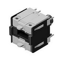
... Switching element for Keylock- and Selector switch 2 positions Terminals PCB terminal Contacts Normally closed Normally open Component layout from page 23, Circuit drawing from page 26 e Typ-Nr. P 71-670.006 1 3 0.005 e Contacts Typ-Nr 71-671.026 1 7 0.005 71-672.026 1 6 0.005 e Contacts Typ-Nr 71-671.026 1 7 0.005 71 17 01.2009 ...
Page 20
... Interlocking pin Continuation see next page Interlocking pin > Illumination Filament lamp Continuation see next page Socket Filament lamp 01.2009 Contacts Typ-Nr 71-672.026 Operating voltage/-current Typ-Nr. 12 VAC/DC 10-1309.1309 14 VAC/DC 10-1310.1319 18 VAC/DC 10-1311.1249 24 VAC/DC 10-1312.1229 28 VAC/DC 10-1313.1209 28 VAC/DC 10-1313.1249 36 VAC/DC 10-1316.1179 36 VAC/DC 10-1316 ...
Page 21
... VAC/DC, 4/8 mA 10-2J19.1049 6 VDC 10-2J06.3149 12 VAC/DC, 7/14 mA 10-2J09.1064 24 VAC/DC, 7/14 mA 10-2J12.1064 28 VAC/DC, 7/14 mA 10-2J13.1064 48 VAC/DC, 4/8 mA 10-2J19.1044 6 VDC 10-2J06.3144 Typ-Nr. 61-9912.0 Typ-Nr. 61-9730 0.002 0.002 0.002 0.002 0.002 0.002 0.002 0.002 0.002 0.002 0.002 0.002 0.002 0.002 0.002 0.002 0.002 ...
Page 22
... Accessories Lamp remover Continuation see next page Lamp remover CAUTION A switching process might be released when replacing the lamp/LED ! Mounting tool Continuation see next page Mounting tool for Indicator 16 mm dia. 20 01.2009 71 e Typ-Nr. 61-9740.0 0.003 e Typ-Nr. 01-907 0.020 ...
Page 23
... Technical Data System switch 71 Switching system Self-cleaning, double-break snap-action switching system with one NC- (Normally closed) and one NO-contact (Normally open). Material Lens Polycarbonat (PC), as per UL 94 V0, or Aluminium anodized Front bezel Polyetherimid (PEI), as per UL 94 V0, or Aluminium anodized Material of contact AgNi, 2 μm gold plated ...
Page 24
... To get an efficient protection, the free-wheeling diode must be connected as close as possible to the inductive load! 0 Switching with inductive load Fig. 1 Switch + Free-wheeling Inductive VDC _ diode load 22 01.2009 Counter emf over load without free-wheeling diode Fig OFF 0 Sveral hundred to several thousend volts dt 71 ...
Page 25
... Illumination element Switching element 1NC+1NO 71-670.006 Switching element 2NC+2NO 71-671.026 71-672.026 Drilling plan (Elementside) Through-connection recommended 14.4 7.2 Hole Ø 1.2 Pad Ø 2.4 X1 Lamp cathode (-) X2 Lamp anode (+) 1-2 Contact normally closed 3-4 Contact normally open 5 Hole for interlocking pin 23 01.2009 71 ...
Page 26
... Mushroom-head pushbutton actuator, flush mounting page 9 | Front bezel set for Mushroom-head pushbutton, flush mounting page 14 +0.2 22 min. Hole spacing 41 mm min. by using front bezel set 61-9934.8 Technical drawing 1 Protective cover, flush mounting page 16 5.5 max 4.5 2 Protective cover, flush mounting page 16 5.5 max 4.5 24 01.2009 71 ...
Page 27
... Blind plug, flush mounting page 16 16.5 min. 2 20.5 max. 1... Mushroom-head pushbutton actuator, flush mounting page 9 10 5.5 max. 1.6 max. +0 Indicator actuator, flush mounting page 8 | Illuminated pushbutton actuator, flush mounting page 8 5.5 max. 1.6 max. +0 Ø Ø 01.2009 ...
Page 28
... Selector switch actuator 2 positions, flush mounting page 11 | Selector switch actuator 3 positions, flush mounting page 11 7 5.5 max. 1.6 max. +0 Circuit drawing 1 Mushroom-head pushbutton actuator, flush mounting page 9 2 Mushroom-head pushbutton actuator, flush mounting page 9 3 Indicator actuator, flush mounting page 8 | Illumination element page 17 4 Illuminated pushbutton actuator, flush mounting page 8 26 01.2009 Ø Ø ...
Page 29
... Keylock switch actuator 3 positions, flush mounting page 10 10 Keylock switch actuator 2 positions, flush mounting page 9 11 Keylock switch actuator 2 positions, flush mounting page 9 12 Keylock switch actuator 3 positions, flush mounting page 10 13 Keylock switch actuator 3 positions, flush mounting page 10 14 Selector switch actuator 2 positions, flush mounting page 01.2009 ...
Page 30
... Selector switch actuator 2 positions, flush mounting page 11 16 Selector switch actuator 3 positions, flush mounting page 11 17 Selector switch actuator 3 positions, flush mounting page 11 18 Selector switch actuator 3 positions, flush mounting page 11 19 Selector switch actuator 3 positions, flush mounting page 11 28 01.2009 71 ...
Page 31
... 61-9933.0 ................................... 14 61-9933.0 ................................... 14 61-9933.1 ................................... 14 61-9933.1 ................................... 14 61-9933.10 ................................. 14 61-9933.10 ................................. 14 61-9934.8 ................................... 14 61-9936.0 ................................... 15 71-600.0 ....................................... 8 71-611.0 ....................................... 8 71-611.0 ....................................... 9 71-612.0 ....................................... 8 71-612.0 ....................................... 9 71-621.0/D ...................................9 71-622.0/D ...................................9 71-623.0/D ...................................9 71-624.0/D ...................................9 71-631.0/D ................................. 10 71-632.0/D ................................. 10 71-633.0/D ................................. 10 71-634.0/D ................................. 10 71-635.0/D ................................. 10 71-636.0/D ................................. 10 71-637.0/D ................................. 10 71-638.0/D ................................. 10 71-639.0/D ................................. 10 71-641.0 ..................................... 11 71-642.0 ..................................... 11 71-651.0 ..................................... 11 71-652.0 ..................................... 11 71-656.0 ..................................... 11 71-658.0 ..................................... 11 71-670.006 ................................. 17 71-671.026 ................................. 17 71-671.026 ................................. 17 71-672.026 ................................. 17 71-672.026 ................................. 18 71-679.0 ..................................... 18 84-9103.7 ................................... 15 29 01.2009 ...
Page 32
... EAO AG Tannwaldstrasse 88 4601 Olten, Switzerland E-mail info@eao.com Website www.eao.com Austria Phone +49 201 Fax +49 201 85 87 210 E-mail sales.ede@eao.com Belgium Phone +32 3 777 82 36 Fax +32 3 777 84 19 E-mail sales.ebl@eao.com China Phone +852 Fax +852 E-mail sales.ehk@eao.com France Phone + Fax + E-mail sales.ese@eao.com ...