HI 11-P1/P3 MOELLER, HI 11-P1/P3 Datasheet - Page 4
HI 11-P1/P3
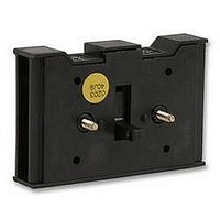
Manufacturer Part Number
HI 11-P1/P3
Description
AUXILIARY CONTACT BLOCK, 1NO/1NC
Manufacturer
MOELLER
Datasheet
1.ZVV-P3ZAV-P3.pdf
(6 pages)
Specifications of HI 11-P1/P3
No. Of Poles
2
Svhc
No SVHC (18-Jun-2010)
Contact Configuration
1 N/O + 1 N/C
Operating Temperature Max
50°C
Operating Temperature Min
-25°C
For Use With
P Motor Disconnect Switches
Lead Free Status / RoHS Status
na


4
Rated operational current 240 V
240 V Contacts
DC−23A, motor load switch L/R
= 15 ms
24 V
Rated operational current
Contacts
48 V
Rated operational current
Contacts
60 V
Rated operational current
Contacts
120 V
Rated operational current
Contacts
240 V
Rated operational current
Contacts
DC−13, Control switches L/R =
50 ms
Rated operational current
Voltage per contact pair in series
Control circuit reliability at 24 V
DC, 10 mA
Notes
Notes
Fault probability
I
I
I
I
I
I
I
e
e
e
e
e
e
e
Quantity 1
Quantity 1
Quantity 2
Quantity 3
Quantity 3
Quantity 5
H
A
A
A
A
A
A
A
V
F
1
10
10
10
5
5
10
32
< 10
operations
For mechanical shock
resistance: T3.../I... >12g
Applies to T0(3).../SVB:
isolating characteristics to
IEC/EN 60947 Ufor rated
operational voltage up to
500 V AC
Applies to rated
uninterrupted current I
the contact: with
T5−4−8344/I5 max. 95 A
For terminal capacity solid,
stranded and flexible:
T0(3), (6), (8)...: Maximum
of 2 cross−section sizes
difference admissible
between 2 conductors
T5(B)−...: Maximum of 1
−5
, < 1 fault in 100000
u
of
Related parts for HI 11-P1/P3
Image
Part Number
Description
Manufacturer
Datasheet
Request
R


Part Number:
Description:
HI SPEED CMOS ANLG SW
Manufacturer:
Vishay
Datasheet:

Part Number:
Description:
HI SPEED COMPARATOR ECL OUTPUT
Manufacturer:
Linear Technology
Datasheet:

Part Number:
Description:
HI/LO SIDE DRVR 8SOIC
Manufacturer:
International Rectifier
Datasheet:
Part Number:
Description:
HI/LO SIDE DRVR 8SOIC
Manufacturer:
International Rectifier
Datasheet:

Part Number:
Description:
HI/LO SIDE DRVR 8SOIC
Manufacturer:
International Rectifier
Datasheet:
Part Number:
Description:
HI SPEED PRECISION JFET OA
Manufacturer:
Linear Technology
Datasheet:

Part Number:
Description:
Hi Bandwidth Quad SPDT I.C.
Manufacturer:
Analog Devices Inc
Datasheet:

Part Number:
Description:
HI RED LED 7 SEG
Manufacturer:
Lite-On Electronics
Datasheet:


Part Number:
Description:
HI D JAX
Manufacturer:
Switchcraft Inc.
Datasheet: