3LD9200-5B SIEMENS, 3LD9200-5B Datasheet

AUXILIARY SWITCH, 1NO/1NC

3LD9200-5B

Manufacturer Part Number
3LD9200-5B
Description
AUXILIARY SWITCH, 1NO/1NC
Manufacturer
SIEMENS
Series
3LD9r
Datasheet

Specifications of 3LD9200-5B

No. Of Poles
2
Contact Configuration
1 N/O, 1 N/C
Lead Free Status / RoHS Status
Lead free / RoHS Compliant
Introduction
Overview
-- Not available
Type
Rated uninterrupted current I
at 35 °C ambient temperature
Rated operational voltage
U
AC-3 motor load switches
Operational switching of individual motors
• At 220 ... 240 V
• At 380 ... 440 V
• At 660/690 V
AC-23A main control switches, maintenance switches
Frequent, but not operational switch-
ing of single motors
• At 220 ... 240 V
• At 380 ... 440 V
• At 660/690 V
Switch versions
Front mounting
• Central
• Four-hole
Floor mounting
• Central
• Four-hole
Distribution board mounting
Molded-plastic enclosures
• Metric screwed glands
Switch accessories
4th pole (neutral conductor)
(leading switch-on,
delayed switch-off)
N terminals
PE-ground terminals
Auxiliary contact elements
• 1 NO + 1 NC
3LD main and EMERGENCY-STOP switches from 16 A to 125 A
17/2
e
Available
SENTRON Switching and Protection Devices — Switch Disconnectors
Siemens LV 1 · 2007
u
A
V
kW
kW
kW
kW
kW
kW
3LD20
16
690
3.0
5.5
5.5
4.0
7.5
7.5
3LD21
25
690
4.0
7.5
7.5
5.0
9.5
9.5
© Siemens AG 2007
3LD22
32
690
5.5
9.5
9.5
6.0
11.5
11.5
3LD25
63
690
11.0
18.5
15.0
11.0
22.0
18.5
3LD27
100
690
18.5
30.0
22.0
18.5
37.0
30.0
--
--
3LD28
125
690
22.0
37.0
30.0
22.0
45.0
--
--
37.0

Related parts for 3LD9200-5B

3LD9200-5B Summary of contents

Page 1

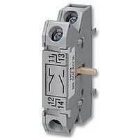
... Molded-plastic enclosures • Metric screwed glands Switch accessories 4th pole (neutral conductor) (leading switch-on, delayed switch-off) N terminals PE-ground terminals Auxiliary contact elements • Available -- Not available 17/2 Siemens LV 1 · 2007 © Siemens AG 2007 3LD21 3LD22 3LD25 690 690 690 4.0 5.5 11 ...

Page 2

... IEC 60947-3/VDE 0660 Part 107 (EN 60947-3) and comply with the conditions for switch disconnectors. The 3LD can be used as • ON-OFF switch • EMERGENCY-STOP switch • Main control switch according to EN 60204-1 17/14 Siemens LV 1 · 2007 © Siemens AG 2007 60204-1 (VDE 0113 Part 1), main control switches are called " ...

Page 3

... Siemens LV 1 · 2007 17/15 ...

Page 4

... Actuators Black Red/yellow (EMERGENCY-STOP) 1) 4th contact element as neutral conductor to be ordered separately, see Accessories for floor mounting. 2) Please order auxiliary switches separately, see Accessories. 17/26 Siemens LV 1 · 2007 © Siemens AG 2007 Base Rated data at DT Order No. terminal 50 ... 60 Hz 380 ... 440 V ...

Related keywords