HA-C1 IDEC, HA-C1 Datasheet - Page 22
HA-C1
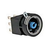
Manufacturer Part Number
HA-C1
Description
CONTACT BLOCK, SPDT, 100mA, SOLDER LUG
Manufacturer
IDEC
Datasheet
1.HA-C1.pdf
(22 pages)
Specifications of HA-C1
No. Of Poles
1
Contact Current Max
100mA
Contact Voltage Ac Max
125V
Contact Voltage Dc Max
30V
For Use With
L6 Series Illuminated Pushbutton / Selector Switches
Lead Free Status / RoHS Status
Lead free / RoHS Compliant


www.idec.com
Pushbutton Assembly
Lamp Installation
Lamps can be replaced in two ways:
1. If contacts are accessible (or pushbutton not installed in a panel) then
it is easiest to first remove the contacts from the operator. This will allow
easy access to the lamp/lamp-holder assembly. Grab lamp, depress
slightly, and turn counter clockwise. Lamp can then be removed by
pushing it back through the lamp holder.
2. If contacts are not accessible, then the lamp can be replaced by first
removing the lens from the operator. Just pull lens straight out either
with a fingernail or optional lens removal tool (MT-101). Lamp/lamp-
holder assembly can then be removed with lamp removal tool (OR-44).
Insert lamp removal tool through operator, depress slightly, turn counter
clockwise, then pull lamp/lamp-holder assembly out. Lamp can then be
removed by pushing it back through the lamp holder.
Engraving Lenses
All buttons and lenses can be engraved directly on the outside surface.
Illuminated lenses also allow for engraving on a plate that is underneath
the colored section of the lens. Remove the colored section of the lens
by pulling on the edge while simultaneously unhooking it from the
latches on the lens holder. The marking plate will then be accessible. It
can then be engraved or a thin marked insert (such as mylar or paper)
can be sandwiched between the marking plate and colored section of
the lens.
Panel Mounting
Before any unit can be mounted into a panel, the contact block must be removed. Slide metal locking lever and pull contact off. Loosen and
remove the locking ring and square anti-rotation ring from the operator and insert operator through panel cutout from the front of the panel.
Slide on anti-rotation ring and tighten locking ring, using locking ring wrench (MT-001). Slide contact block onto operator, observing TOP
marking on both parts. Slide metal locking lever in direction indicated by LOCK. The yellow plastic safety lever lock can then be snapped onto
the locking lever; this will prevent vibration or maintenance actions from releasing the contact from the operator.
PCB Mounting
Being able to separate the contacts from the operator allows for assem-
bly of the front panel components (operator and lens) to be performed in
tandem with the PC board assembly and soldering. For applications
where multiple rows of pushbuttons are mounted closely together, or
where other components may obstruct access to the contact locking
lever, be sure to include access holes in the PC board (refer to PC board
layout dimensions for location). Also be sure to allow for space above
and to the side of contact to ensure that no components block the con-
tact block locking lever. PC board pins are designed to rest on the PCB,
take this into consideration to ensure that pins do not short closely
spaced traces.
Miniature Switches & Pilot Devices
USA: (800) 262-IDEC or (408) 747-0550, Canada: (888) 317-IDEC
General Instructions
Color Lens
Recess
Engraving
Area
Marking Plate Lens Holder
Latches
ø16mm - L6 Series
A2-51
A2
Related parts for HA-C1
Image
Part Number
Description
Manufacturer
Datasheet
Request
R

Part Number:
Description:
HA-C5 L6 Contact SPDT Silver Solder
Manufacturer:
IDEC
Datasheet:

Part Number:
Description:
CONTACT BLOCK, DPDT, 100mA, SOLDER LUG
Manufacturer:
IDEC
Datasheet:

Part Number:
Description:
CONTACT BLOCK, DPDT, 5A, SOLDER LUG
Manufacturer:
IDEC
Datasheet:
Part Number:
Description:
CONTACT BLOCK, SPDT, 100mA, SOLDER LUG
Manufacturer:
IDEC
Datasheet:

Part Number:
Description:
CONTACT BLOCK, SPDT, 3A, THROUGH HOLE
Manufacturer:
IDEC
Datasheet:
Part Number:
Description:
Cover, Switch; Not Applicable; Yellow; HA Series; IP20
Manufacturer:
IDEC Corporation
Datasheet:
Part Number:
Description:
Cable; Between IDEC MicroSmart (port 1 or 2) and HG2F/3F/4F; 5 ft.
Manufacturer:
IDEC Corporation
Datasheet:

Part Number:
Description:
88SE6440 PCIe by 4, 3Gpbs SAS/SATA 4 internal ports Controller Board
Manufacturer:
Marvell
Part Number:
Description:
INDICATOR INCANDESCENT LAMP, GREEN
Manufacturer:
IDEC
Datasheet:

Part Number:
Description:
LAMP, INDICATOR, INCAND, AMB
Manufacturer:
IDEC
Datasheet:
Part Number:
Description:
LAMP, INDICATOR, INCAND, GRN
Manufacturer:
IDEC
Datasheet:
Part Number:
Description:
LAMP, INDICATOR, INCAND, GRN
Manufacturer:
IDEC
Datasheet: