9001K35H2 SQUARE D, 9001K35H2 Datasheet - Page 166
9001K35H2
Manufacturer Part Number
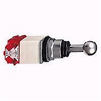
9001K35H2
Description
Joystick Switch Operator
Manufacturer
SQUARE D
Type
Joystickr
Specifications of 9001K35H2
Actuator
Non-Illuminated
Actuator Type
Joystick
Bezel
Chrome Plated
Body Style
Standard
Brand/series
K
Contact Form
2 N.O./2 N.C.
Contacts
Silver Alloy
Current, Rating
10 A
Enclosure Rating
NEMA 4/13
Head Type
Round
Knob Type
Without Latch
Mounting Hole Size
30 mm
Mounting Type
Panel
Number Of Positions
5
Operation
Momentary
Special Features
Spring Return (To Center)
Terminal Type
Screw Clamp
Voltage Rating
600 V
For Use With
30mm Control And Signaling Units
Lead Free Status / RoHS Status
Lead free / RoHS Compliant


Push Button and Operator Interface - Type KX 30 mm
Selector Switch Selection Guide
Shown below is a simplified method of selecting a selector
switch to meet almost any combination of contact sequences.
Step No. 1
Determine the contact sequence(s) required. Set up a target ta-
ble like the one shown for the example below.
Example:
Step No. 2
Look for a cam type common to all sequences in Table 1, 2 or
3. For the example above, Table 2 would be used. For the con-
tact sequences A(1 0 0), B(0 1 0) and C(0 0 1) of the example
above, cam types F and L are common to all 3 sequences.
Step No. 3
Next, the cam type common to all the sequences (If several
cam types are common, choose one.) is used to find the oper-
ator type number. Go to the proper page number as indicated
in the table below:
If for the example above:
A manual return operator with a standard black knob is required and
Step No. 4:
Determine the contact blocks required by using the same table
used for Step No. 2.
If for the example above:
The F cam type were chosen:
The L cam type were chosen:
One Type KA1 double circuit block can be used in place of one
Type KA2 single circuit block and one Type KA3 single circuit
block mounted on the same side.
“H” Numbers . . . . . . . . . . . . . . . . . . . . . . . . . . . . . . . . . . . . . . . . . . . Page 174
Outline Dimensions . . . . . . . . . . . . . . . . . . . . . . . . . . . . . . . . . . . . . . . Page 176
166
Number of Positions
If the F cam type were chosen, the operator type number would be:
If the L cam type were chosen, the operator type number would be:
A 9001KA3 mounted on side no. 2 would be used for sequence A(1 0 0).
A 9001KA3 mounted on side no. 1 would be used for sequence B(0 1 0).
A 9001KA2 mounted on side no. 1 or 2 would be used for sequence
C(0 0 1).
A 9001KA2 mounted on side no. 2 would be used for sequence A(1 0 0).
A 9001KA2 mounted on side no. 1 or a 9001 KA3 mounted on side no.
2 would be used for sequence B(0 1 0).
A 9001KA3 mounted on side no. 1 would be used for sequence C(0 0 1).
Sequence
© 1999-2005 Schneider Electric All Rights Reserved
Contact
A
B
C
Type KX Line – Class 9001 Type KXSDFB (from page 167)
Type KX Line – Class 9001 Type KXSDLB (from page 167)
2
3
4
KA1
1
0
0
Push Button Line
1 – contact closed
0 – contact open
=
=
Type KX
Type KX
Type KX
KA3
+
+
KA2
0
1
0
Page Number
167
167
167
0
0
1
Table 1 – 2 Position Selector Switch
Table 2 – 3 Position Selector Switch
Table 3 – 4 Position Selector Switch
✻
1
0
0
0
1
1
0
0
1
0
1
0
1
1
contact sequence
1
0
0
1
0
1
The KA5 must be the last block on either side. If more than one KA5 is required on either
side – contact your local Square D sales office.
If you require
contact sequence
contact sequence
1
0
If you require
If you require
0
1
0
0
0
1
1
0
1
1
0
1
1
0
0
1
0
1
1
0
0
0
1
0
0
0
1
1
1
1
1
0
0
1
0
0
0
1
1
0
0
1
0
1
0
1
1
1
0
1
0
0
1
0
1
1
with cam type
Use Sel. Sw.
B C
B
B
B
B
B
with cam type
C
C
C
Use Sel. Sw.
H
H
H
H
H
H
H
H
H
H
H
H
H
H
with cam type
D E
D E
D
D
D E
D E
Use Sel. Sw.
E
D
E
D
E
E F G J
F
F
F
G
G J
G
G J
G
J L
J
J L
L
L
L
L
Use contact
block type
(A) KA3
(B) KA2
(C) KA2
(D) KA3
Use contact
M
M
M
M
KA5 ✻
KA5 ✻
block type
A, B & C Wired in Parallel
B, C & D Wired in Parallel
Use contact
C & D Wired in Parallel
block type
A & D Wired in Parallel
A & B Wired in Parallel
B & C Wired in Parallel
A & C Wired in Parallel
B & D Wired in Parallel
KA3
KA2
KA2
KA3
KA5 ✻
KA5 ✻
KA5 ✻
KA5 ✻
KA5 ✻
KA5 ✻
KA5 ✻
KA2
KA2
KA3
KA3
KA2
KA2
KA3
KA3
KA2
KA3
KA3
KA2
KA2
KA3
KA2
KA3
KA3
(See page 174)
(See page 174)
(See page 174)
Mount on
side No.
Mount on
Mount on
side No.
side No.
1 or 2
1 or 2
1 or 2
1 or 2
1 or 2
1 or 2
2
1
2
1
2
1
1
2
1
2
2
1
2
1
2
1
1
2
1
2
2
1
2
1
1
1
2
2
04/2005
Related parts for 9001K35H2
Image
Part Number
Description
Manufacturer
Datasheet
Request
R


Part Number:
Description:
Pushbutton, Non-Illum'd Red "STOP", Momentary, 1NO-1NC, Square 30mm, 10A, 600V
Manufacturer:
SQUARE D
Datasheet:

Part Number:
Description:
KITS,TWIDO? PROGRAMMABLE CONTROLLERS,KITS,TWIDOPACK STARTER KIT - ADVANCED LEVEL,PROGRAMMABLE CONTROLLERS,TWIDO? PROGRAMMABLE CONTROLLERS ,SQUARE D
Manufacturer:
SQUARE D

Part Number:
Description:
LAMPS,INDICATOR,STACKABLE,LAMPS, STACKABLE INDICATOR,VISUAL INDICATING SIGNALS,XVB SERIES INDICATING BANKS ,SQUARE D
Manufacturer:
SQUARE D
Part Number:
Description:
LAMPS,INDICATOR,STACKABLE,LAMPS, STACKABLE INDICATOR,VISUAL INDICATING SIGNALS,XVB SERIES INDICATING BANKS ,SQUARE D
Manufacturer:
SQUARE D
Datasheet:
Part Number:
Description:
CB ACCESSORY, UNDERVOLTAGE TRIP 48V DC
Manufacturer:
SQUARE D
Datasheet: