LH1523BAC Vishay, LH1523BAC Datasheet - Page 2
LH1523BAC
Manufacturer Part Number
LH1523BAC
Description
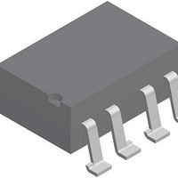
IC,Normally-Closed PC-Mount Solid-State Relay,2-CHANNEL,SO
Manufacturer
Vishay
Datasheet
1.LH1523BACTR.pdf
(4 pages)
Specifications of LH1523BAC
Load Voltage Rating
200 V
Load Current Rating
0.2 A
Contact Form
2 Form B
Output Device
MOSFET
Maximum Operating Temperature
+ 85 C
Minimum Operating Temperature
- 40 C
Package / Case
PDIP-8
Output Type
AC, DC
Mounting Style
SMD/SMT
Case Color
Black
Relay Type
Solid State
Lead Free Status / RoHS Status
Lead free / RoHS Compliant
Lead Free Status / RoHS Status
Lead free / RoHS Compliant, Lead free / RoHS Compliant
Available stocks
Company
Part Number
Manufacturer
Quantity
Price

Part Number:
LH1523BACTR
Manufacturer:
VISHAY/威世
Quantity:
20 000


LH1523BB, LH1523BAC, LH1523BACTR
Vishay Semiconductors
Notes
• Stresses in excess of the absolute maximum ratings can cause permanent damage to the device. Functional operation of the device is not
(1)
(2)
Note
• Minimum and maximum values are testing requirements. Typical values are characteristics of the device and are the result of engineering
www.vishay.com
2
THE PRODUCT DESCRIBED HEREIN AND THIS DATASHEET ARE SUBJECT TO SPECIFIC DISCLAIMERS, SET FORTH AT
ABSOLUTE MAXIMUM RATINGS (T
PARAMETER
INPUT
LED continuous forward current
LED reverse voltage
OUTPUT
DC or peak AC load voltage
Continuous DC load current,
one pole operating
Continuous DC load current,
two poles operating
Peak load current (single shot)
SSR
Ambient temperature range
Storage temperature range
Pin soldering temperature
Input to output isolation voltage
Pole-to-pole isolation voltage (S1 to S2)
(dry air, dust free, at sea level)
Output power dissipation (continuous)
ELECTRICAL CHARACTERISTICS (T
PARAMETER
INPUT
LED forward current, switch turn-on
LED forward current, switch turn-off
LED forward voltage
OUTPUT
On-resistance
Off-resistance
Off-state leakage current
Output capacitance
TRANSFER
Capacitance (input to output)
SWITCHING CHARACTERISTICS (T
PARAMETER
Turn-on time
Turn-off time
implied at these or any other conditions in excess of those given in the operational sections of this document. Exposure to absolute
maximum ratings for extended periods of the time can adversely affect reliability.
Breakdown occurs between the output pins external to the package.
Refer to reflow profile for soldering conditions for surface mounted devices (SMD). Refer to wave profile for soldering conditions for through
hole devices (DIP).
evaluations. Typical values are for information only and are not part of the testing requirements.
(2)
For technical questions, contact:
(1)
,
Dual 1 Form B Solid State Relay
This datasheet is subject to change without notice.
t = 1 s, I
amb
amb
I
amb
L
I
I
TEST CONDITION
I
I
F
F
I
F
F
= ± 200 mA, t = 10 ms
F
I
TEST CONDITION
TEST CONDITION
= 5 mA, V
= 5 mA, V
F
= 10 mA, I
= 10 mA, I
= 25 °C, unless otherwise specified)
= 25 °C, unless otherwise specified)
t = 10 s max.
= 0 mA, I
= 5 mA, V
t = 100 ms
= 25 °C, unless otherwise specified)
I
I
R
L
V
ISO
I
L
V
50 μA
F
10 μA
ISO
= ± 150 V
= 10 mA
= 10 μA max.
= 1 V
L
L
L
L
L
= ± 100 V
= ± 200 V
L
= 50 mA
= 50 mA
= 50 mA
= 50 V
optocoupleranswers@vishay.com
SYMBOL
SYMBOL
SYMBOL
R
R
I
I
C
T
P
C
V
t
t
Fon
Foff
V
T
T
I
on
off
V
V
ON
Off
O
amb
I
diss
IO
I
I
I
ISO
F
O
stg
sld
F
L
L
P
R
L
MIN.
MIN.
1.15
0.2
0.1
- 40 to + 125
- 40 to + 85
VALUE
3750
1600
200
200
140
400
260
600
50
5
TYP.
TYP.
1.22
0.07
0.9
1.4
10
50
1
3
1
2
www.vishay.com/doc?91000
Document Number: 83822
MAX.
MAX.
Rev. 1.5, 10-Mar-11
1.45
15
2
1
3
3
UNIT
V
mW
mA
mA
mA
mA
°C
°C
°C
RMS
V
V
V
UNIT
UNIT
G
mA
mA
μA
ms
ms
pF
pF
V
Related parts for LH1523BAC
Image
Part Number
Description
Manufacturer
Datasheet
Request
R

Part Number:
Description:
Dual 1 Form B Solid State Relay
Manufacturer:
Vishay
Datasheet:
Part Number:
Description:
357-036-542-201 CARDEDGE 36POS DL .156 BLK LOPRO
Manufacturer:
Vishay
Datasheet:
Part Number:
Description:
357-036-542-201 CARDEDGE 36POS DL .156 BLK LOPRO
Manufacturer:
Vishay
Datasheet:
Part Number:
Description:
357-036-542-201 CARDEDGE 36POS DL .156 BLK LOPRO
Manufacturer:
Vishay
Datasheet:
Part Number:
Description:
357-036-542-201 CARDEDGE 36POS DL .156 BLK LOPRO
Manufacturer:
Vishay
Datasheet:
Part Number:
Description:
357-036-542-201 CARDEDGE 36POS DL .156 BLK LOPRO
Manufacturer:
Vishay
Datasheet:
Part Number:
Description:
357-036-542-201 CARDEDGE 36POS DL .156 BLK LOPRO
Manufacturer:
Vishay
Datasheet:
Part Number:
Description:
357-036-542-201 CARDEDGE 36POS DL .156 BLK LOPRO
Manufacturer:
Vishay
Datasheet:
Part Number:
Description:
357-036-542-201 CARDEDGE 36POS DL .156 BLK LOPRO
Manufacturer:
Vishay
Datasheet:
Part Number:
Description:
357-036-542-201 CARDEDGE 36POS DL .156 BLK LOPRO
Manufacturer:
Vishay
Datasheet:
Part Number:
Description:
357-036-542-201 CARDEDGE 36POS DL .156 BLK LOPRO
Manufacturer:
Vishay
Datasheet:
Part Number:
Description:
357-036-542-201 CARDEDGE 36POS DL .156 BLK LOPRO
Manufacturer:
Vishay
Datasheet:
Part Number:
Description:
357-036-542-201 CARDEDGE 36POS DL .156 BLK LOPRO
Manufacturer:
Vishay
Datasheet:
Part Number:
Description:
357-036-542-201 CARDEDGE 36POS DL .156 BLK LOPRO
Manufacturer:
Vishay
Datasheet:
Part Number:
Description:
357-036-542-201 CARDEDGE 36POS DL .156 BLK LOPRO
Manufacturer:
Vishay
Datasheet: